- Home Page
- Company Profile
-
Our Products
- Circuit breaker
- FHP36050 (50A) CIRCUIT BREAKER
- Air Circuit Breaker (Acb)
- SIEMENS AIR CIRCUIT BREAKER
- Air Circuit Breaker
- Abb Vacuum Circuit Breaker ( HT BREAKER)
- FAL36100 (100A) CIRCUIT BREAKER
- KA36100 (100A) CIRCUIT BREAKER
- FA34060 (60A) CIRCUIT BREAKER
- FHP36015 (15A) CIRCUIT BREAKER
- CUTLER HAMMER ND 50K 1200A 3 POLE CIRCUIT BREAKER
- SQUARE D AL600LI5T CIRCUIT BREAKER MCCB
- SCHNEIDER POWERPACT QJ 200 CIRCUIT BREAKER
- ABB XT4H 250 (CCBA039143) CIRCUIT BREAKER
- ABB XT4H 250 (CCAA041527) CIRCUIT BREAKER
- SQUARE D HD150 (HDL36150) 150A CIRCUIT BREAKER
- FPE NE233040 3 POLE AIR CIRCUIT BREAKER
- SQUARE D POWER PACT HD 150 HDL36150 150A 3 POLE CIRCUIT BREAKER
- SQUARE D KH70A AL250KA 3P 70A CIRCUIT BREAKER
- DISJONCTEUR KAL36125 125A 3P CIRCUIT BREAKER
- ALLEN BRADLEY 140U-Q6X3 600A 3POLE MCCB
- ALLEN BRADLEY 140U-Q3X3 600A 3POLE MCCB
- CUTLER HAMMER HND 65K HND312T32W 1200A 3POLE CIRCUIT BREAKER
- CUTLER HAMMER ND 50K ND312T56W 1200A 3POLE CIRCUIT BREAKER
- CUTLER HAMMER HJD 65K HJD3250F 250A 3POLE CIRCUIT BREAKER
- CUTLER HAMMER DK-K DK3400KX02Y 12D08 400A 3POLE MCCB CIRCUIT BREAKER
- ABB ESB24-30-01 CONTACTOR
- FANUC PLC & HMI
- Industrial Automation
- ROBO CYLINDER RCP-C-SA6A
- Power Supply
- NAIS BFVCE0404A VF-C INVERTER DRIVE
- HMI Panels
- SCHNEIDER BSH1002P11A2A SERVO MOTOR
- FUJI NP1PS-32 PLC
- SWISSBIT 5CFCRD.1024-06 FLASHCARD
- SCHNEIDER PAC DRIVE C200/10/1/1/1/00
- DELTA ASD-A2-0721-U SERVO DRIVE
- Ac/dc Drives (Vfd)
- Soft Starters
- AC Drives
- Siemens Power supply 6Ep0 133-3AA00+0AA1
- PLC Controller
- ELECTRONIC SOFT STARTER
- VACON AC DRIVE
- ABB 1SFN156170R7106
- YOKOGAWA YS1310
- KUKA 69-327-923
- Electrical IGBT
- DC Drives
- KUKA 69-327-921
- Electronic Power Supply Unit
- KUKA 69-334-285
- SANYO DENKI IPY PYRE213002
- Conzerv Em 3360
- Emerson Emu10
- Himap Relay
- LEADSHINE L5-400
- DELEM DM02-K-SN 48769
- ACG EMT3070B
- VECON LEVI430T
- ROMACO GF0-57SQD-002
- SME 62597-CFAI CF CARD
- JUMO SCREEN 706510 25 22 020 261 266
- FWA-CML40-IL-02V01-DO-0008 SANDISK
- SIEMENS 6ES7 951-1AJ00-0AA0 MEMORY CARD
- LS 14250 SAFT BATTERY
- SL-750 XTSX INORGANIC LITHIUM BATTERY
- VIPA 951-0KJ00 MEMORY CARD
- HELMHOLZ 700-953-8LJ11 MEMORY CARD
- SEW UFP11A-00 PROFIBUS DP-V1
- FESTO CPV10-GE-MP-6 PLC
- MODULOFACE CF-2009 PLC
- Primary lithium battery SAFT LS 26500
- AUTONICS MD5-HF14 Stepper motor drivers
- RISH MASTER 3480 MULTI-FUNCTION METER
- TADIRAN SL-350 PEWB BATTERY
- MTL 787+ SHUNT-DIODE SAFETY BARRIER
- BUSSMANN CH141D 14x51
- SAFT LS-14500 Li-SOCI2 Battery
- ABB PSTX470-600-70 / 1SFA898116R7000 470A SOFT STARTER
- Dolphin Automation N8GS1 Inductive 8 mm Proximity Sensor
- KEB 00.F4.010-7009 BUS OPERATOR RS 485
- ICP COM RS-485 -7051D MODULE
- WOODWARD ESYGEN 3200 (07741590000112) PCB BOARD
- ABB 3BHE028767R0201 PCB BOARD
- PARKER 6901-00-G OPERATOR KEYPAD
- ABB PSR6-600-70 SOFT STARTER
- ENCLOSURE SK3110 INTERNAL THERMOSTAT
- RISHABH E15-4A13 E70////E CURRENT TRANSDUCER
- MASIBUS 85XX CHANNEL PROCESS SCANNER
- ABB REJ601BD446NB1NH PROTECTION RELAY
- SILICON DRIVE SSD-C64M-3876
- ABB PSRC72-600-70 SOFT STARTER
- AMCI 7662 SR.NO-12100189 MODULE
- SILICON SSD-C51M-3500 SILICONDRIVE
- DELTA VFD004L21A VFD
- MICOM P342311A2M0350J (SER.NO:- 31612943/12/10) (DAMAGE) PROTECTION RELAY
- TAIYO DS-21-2F AUTOMATIC VOLTAGE REGULATOR
- SIEMENS 7MF0300-1FE01-5DM2-Z TRANSMITTER FOR PRESSURE
- ZOTUP SPD L 25-100 230 t ff 3+1 PLC
- S.I TECH MODEL 2145 PROFIBUS DP MINI OPTICAL BIT-DRIVER
- TMEIC 3KZA0247A-H01 PCB BOARD
- MTL 787S+ SHUNT-DIODE SAFETY BARRIER
- LG-OTIS FDA-3010P SERVO DRIVE
- BENDER RCMA-472LY-21 RESIDUAL CURRENT MONITOR
- DELTA ASD-B2-1021-B SERVO DRIVE
- GE PSU MULTILIN I/O RATINGS REFER TO MANUAL
- DELTA ASD-B2-3023-B SERVO DRIVE
- DELTA ASD-A2-1021-L SERVO DRIVE
- ASHIDA ADR245B-B-0-0-0-0-0-0-2-2-2-B PROTECTION RELAY
- PLATINUM COMPACT FLASH CARD 256MB
- SCHNEIDER BMH1401P11A1A (SN:-2504068166) SERVO MOTOR
- SCHNEIDER BMH1401P11A2A SERVO MOTOR
- SINRO SRD02-08230FK2 VARIABLE AIR DAMPER MOTOR
- SCHNEIDER BSH0703P1JA2A SERVO MOTOR
- PHOENIX CONTACT VAL-MS 320ST F3J-349 SURGE PROTECTION CONNECTOR
- PHOENIX CONTACT VAL-MS 320ST F3J-06 SURGE PROTECTION CONNECTOR
- Switchgear and Allied Products
- GE-FANUC PLC & HMI
- GE FANUC IC693MDL940E
- GE FANUC 693MOL645
- GE FANUC IC693APU300F
- GE FANUC IC693MDL730F
- GE FANUC 693BEM331
- GE FANUC IC693CPU331-CD
- GE FANUC IC693MDL655F
- GE FANUC IC693MDL646C
- GE FANUC IC693MDL655E
- GE FANUC IC693APU300H
- GE FANUC IC697BEM713
- GE FANUC IC693CPU363-CK
- GE FANUC IC693CPU352
- GE FANUC IC693MOL740
- GE FANUC IC697PWR711
- GE FANUC IC693MAR590
- GE FANUC IC694ALG223
- GE FANUC IC693PWR330H
- GE FANUC IC698CPE030
- GE FANUC IC693MDL646D
- GE FANUC IC200PWR0010
- GE FANUC IC698CPE40
- GE FANUC IC200UEX214
- GE FANUC IC693ALG390
- GE FANUC IC695CPU315
- GE FANUC IC693MDL930
- GE FANUC IC200MDL742C
- GE FANUC E208879
- GE FANUC IC697BEM731
- GE FANUC IC200MDD844F
- GE FANUC IC697BEM711
- GE FANUC IC200UEX264
- GE FANUC IC200MDL750E
- GE FANUC IC693PWR3215
- GE FANUC IC697CMM741
- GE FANUC IC660BBD110
- GE FANUC IC693MDL 740E
- GE FANUC IC660BBS103
- GE FANUC VERSAMAX IC200UDD110-BA
- GE FANUC IC693CPU363-BE
- GE FANUC IC695CHS012
- GE FANUC IC693APU300J
- GE FANUC IC693CPU311
- GE-FANUC IC693MDL940H
- GE FANUC IC693CPU363-BH
- GE FANUC IC693MDL742G
- GE FANUC IC695CPE310
- GE FANUC IC200UDD040
- GE FANUC IC693MDL742J
- GE FANUC IC698CPE010
- GE FANUC IC693MOL646
- GE FANUC 693-CPU363
- GE FANUC IC693-CMM321
- GE FANUC IC693MDL740F
- GE FANUC IC693MDL940D
- GE FANUC IC693MDL740E
- GE FANUC IC693PWR321X
- GE IC693ALG392B
- GE FANUC IC693MDL231C
- GE IC693CPU331S
- GE FANUC IC693MDL930C
- GE FANUC IC693MDL740G
- GE FANUC IC693PWR321AA
- INNO XLC-30-300P2 SAFETY LIGHT CURTAIN SENSOR
- Electrical Contactor
- YASKAWA SERVO DRIVE SERVO MOTOR
- YASKAWA SGDA-08ASP
- YASKAWA V41-003
- YASKAWA SGDV-120A01A002000 SERVO DRIVE
- YASKAWA SGMJV-08ADD6E
- YASKAWA V1000
- YASKAWA CIMR-VT4A0011BAA
- YASKAWA A1000
- YASKAWA SGDH-02AE
- YASKAWA SGD75-7R6A00A002
- YASKAWA SGDH-50DE
- YASKAWA SGDE-04VS
- YASKAWA SGDH-50AE
- YASKAWA SGMGH-09DCA6F-OY
- SERVOPACK SGDH-15DE-OY
- YASKAWA SGDH-75DE
- YASKAWA SGMGV-20ADC61
- YASKAWA CIMR-F7A4011
- YASKAWA CACR-SR15VE12MY11
- YASKAWA SGDV-1R9D11A020000
- YASKAWA SGDM-15DN
- YASKAWA CIMR-PBA23P7T
- YASKAWA CIMR-PBA22P2T
- YASKAWA SGDV-2R8A11A SERVO DRIVE
- Control Panels
- Main Control Panel
- Motor Control Center(Mcc) Panels
- Power Control Center(Pcc) Panels
- Automatic Power Factor Control (Apfc) Panels
- APFC Control Panel
- MCC Control Panel
- Load Sharing/synchronizing Panels
- 11kv-33kv Ht Vcb Panels
- Flame Proof Panels
- Plc Panels
- Ht Ngr Panels
- Auto Mains Failure Panels
- Distribution Panels
- APFC Capacitor Panel
- Bus Ducts
- Control Desks
- REXROTH SERVO DRIVE, SERVO MOTOR , CNC SPARE PARTS
- REXROTH VCCP02.2DRN-003-SR-NN-PW
- REXROTH DRIVE DKC01 3-040-FW
- REXROTH DKCXX.3-040-7
- REXROTH DRIVE BZM01 3-01-07
- REXROTH RD500
- REXROTH HVR03 2-W045N
- REXROTH HDS03 2-W975N-HS45-0
- REXROTH HDS02 2-W040N-HS12-0
- REXROTH HCS02.1E-W0070
- REXROTH DKCX.3-100-7
- REXROTH HCS02.1E-W0070-A-03-NNNN
- REXROTH HCS02.1E-W0028
- REXROTH CML40.1-NP-220-NA-NNNN-NW
- REXROTH DKC10.3-012-3-MGP-01VRS SERVO DRIVE
- MICOM P342311A2M0350J (DISPLAY DAMAGE) PROTECTION RELAY
- REXROTH DKC02.3-040-7-FW SERVO DRIVE
- REXROTH PNEUMATIK 335540 4512
- Transformer and Transformer Components
- KOLLMORGEN SERVO DRIVE, SERVO MOTOR
- Servo Start Tm 603 S60300
- KOLLMORGEN PRD-PE205S0H-10 SERVO DRIVE
- KOLLMORGEN S30301-NA
- KOLLMORGEN DMC2 50412
- KOLLMORGEN 6SM 77S-3.000-09-V
- KOLLMORGEN DMC2 50720P
- KOLLMORGEN 6SM 57M-3.000-426
- SERVO STAR SC1E06260
- KOLLMORGEN S700
- KOLLMORGEN S74801 NANANA
- Servo Start Tm 606 S60600
- Servo Start Tm 606-as S60601
- Servo Start Tm 610-as S61001
- Kollmorgen Servo Start Tm 606
- Kollmorgen Servo Start Tm 606-as
- Kollmorgen Servo Start Tm 610-as
- Kollmorgen Servo Start Tm 603
- LENZE SERVO DRIVE, SERVO MOTOR AND CNC SPARE PARTS
- LENZE EZAEBK1001 Keypad x400 operator panel
- LENZE E82EV751-4C INVERTER DRIVE
- LENZE E82EV551_4C INVERTER DRIVE
- LENZE E82EV551_2C200 INVERTER AC DRIVE
- LENZE E82EV222-2C000 DRIVE
- Evs9322-es 45168378
- Evs9322-es 45456568
- Evs9322-es 1513038
- LENZE E82EV152_4B
- LENZE E82EV302_4C200
- LENZE 8200 VECTOR
- LENZE 8221MP
- LENZ D-31855
- LENZE D-31763
- Evs9322-es 1518140
- Evs9322-es 1291344
- LENZE E82EV152_4C
- LENZE E82EV251
- E82ev552-4c200 2815253
- LENZE E82EV402_4C
- Lenze E84abbne7524vn0
- LENZE EVS9322-CVSV003
- LENZE E82EV751-2C INVERTER DRIVE
- LENZE E82EV371_2C INVERTER DRIVE
- LENZE 31855 AERZEN DRIVE
- LENZE EPZ-10203 SERVO DRIVE
- LENZE E84AVSCE1834VB0 DRIVE (DAMAGE)
- FANUC SERVO DRIVE SERVO MOTOR AND CNC SPARE PARTS
- FANUC A068-6089-H102
- FANUC AIF 22-3000
- FANUC CX0-104B
- FANUC A06B-6089-H106
- GE FANUC IC200UDD064
- FANUC A14B-0076-B001
- FANUC AIF01A
- FANUC A6-3000
- FANUC AO68-6132-H002
- FANUC A06B-6089-H104
- FANUC A IS 8-4000
- FANUC A40-2000
- FANUC A0R16G
- FANUC AID32f1
- FANUC A05B-2500-C001
- FANUC A06B-6089-H206
- FANUC A06B-6066-H004
- FANUC CX0-109F
- FANUC A02B-0228-B505
- FANUC A06B-6066-H006
- FANUC A03B-0807-C156
- FANUC A02B-0130-B505
- Electrical Capacitors
- FAGOR SERVO DRIVE,SERVO MOTOR AND CNC SPARE PARTS
- Electric Motors and Engines
- PARKER SERVO DRIVE,SERVO MOTOR AND CNC SPARE PART
- PARKER 590P-53311020-P00-U4A0
- PARKER 598P-53260010-TP00-U4A0
- PARKER 590P-53350041-P00-U4A0
- PARKER 590P-53350041-P00-U0V0
- PARKER HID5CS/S4
- PARKER HANNIFIN S.P.A 07030050
- PARKER E234325
- PARKER 590P-53270020-P00-U4A0
- PARKER 590P-53316520-P00-U4A0
- PARKER 590P-53318032-P00-U4A0
- PARKER 690-432120B0-B00P00-A400
- PARKER 690-431950B0-B00P00-A400
- PARKER DRIVE 590P-53350042-P00-U4A0
- MCCB Switches
- BELDOR SERVO DRIVE,SERVO MOTOR AND CNC SPARE PART
- Relay
- ABB REL6704200244295-010 PROTECTION RELAY
- Icc211 For current output icc211-i1-01
- TRANSFORMER PROTACTION RELAY TR-7570
- VAMP 57 PROTECTION RELAY
- MICOM P642912A3M0050P RELAY
- Current Transmitter 0208120020
- MICOM P343211E2M0320J RELAY
- Over Current Earth Fault Relay 03118738
- C.t.connections For Oc Relay Adr111a
- SEL-751A FEEDER PROTECTION RELAY 751A01D0X1D71810100
- Instantaneously Under Voltage Vag21zg8382g(M)
- SIEMENS 7SD5221-5AB29-0CK0/GG (DISPLAY DAMAGE) MULTI TERMINAL LINE PROTECTION
- ABB REX521CHHPSH02D RELAY
- SIEMENS 7XT3400-0CA00 BB BAND PAST FILTER
- Genset Controller 0302 - 2101
- ABB RET521 1MRK001530-AC RELAY
- CSENex- 101 s-d-c-l
- ABB REF615E E HBFCACABNCA1BNN1XE RELAY
- COSEL AD480-24
- ENERCON SMART DEMAND CONTROLLER EM 3460 RELAY
- ABB REL6704200298964-010 PROTECTION RELAY
- ABB REL650AISCWO18I0054 PROTECTION RELAY
- ABB RET670 (BIG SCREEN) PROTECTION RELAY (ONLY DISPLAY)
- SIEMENS 7SJ6221-5EB90-1FC0FF PROTECTION RELAY
- ABB RET6704200883263-030 PROTECTION RELAY
- ABB RED670 (BIG SCREEN) PROTECTION RELAY (ONLY DISPLAY)
- SIEMENS 7UM6211-5EB92-0AA0/FF (BF1105147780) GENERATOR PROTECTION RELAY
- VAMP 50 V50-005519 RELAY
- SANMOTION QS1A03AA
- ABB REG670 BIG PROTECTION RELAY (ONLY DISPLAY)
- Trip Circuit Supervision Relay Vax31zg8074b(M)
- Easun Reyrolle Br1042389
- MPCB (MOTOR PROTACTION CIRCUIT BREAKER)
- AE Contacts Relay AVA33
- OVER LOAD REALY-CT REALY
- Schneider Multifunction Relay EOCR-FDE
- SIEMENS 7UM6221-6EB92-0CB0/FF
- SIEMENS 7VK6101-6AB92-4YC0/EE
- SIEMENS 7UM6215-2EC02-3AA0/EE
- SIEMENS 7SD6101-5BB99-0BA0/EE
- SIEMENS 7SJ6111-5EB00-1FB0/EE
- SIEMENS 7SJ6221-5EB90-1FC0/FF
- SIEMENS 7VE6320-5EB99-1CA0/DD
- SIEMENS 7SJ6612-5EB90-1HF0/BB
- SIEMENS 7SJ6211-5EN32-1FG1/DD
- SIEMENS 7SJ6021-5EB00-1FA0/CC
- SIEMENS 7SJ6005-5EA00-0DA0/BB
- SIEMENS 7SJ6021-2EB20-1FA0/CC
- SIEMENS 7SJ6001-5EA00-0DA0/BB
- SIEMENS 7SJ8031-5EB90-1FC0/BB
- SIEMENS 7SJ6021-4EB20-1HA0/CC
- ABB REG670AISCWO16I0828 PROTECTION RELAY
- ABB REF541KM115AAAA PROTECTION RELAY
- ABB REM545BG225AAAA PROTECTION RELAY
- ABB REL6704201071001-020 PROTECTION RELAY
- ABB REL6704200660374-020 PROTECTION RELAY
- ABB RET6704200883263-020 PROTECTION RELAY
- ABB RET6704201173079-10 PROTECTION RELAY
- MICOM P632-34901040-308-407-630-463-947 PROTECTION RELAY
- ABB SPAJ 140 C PROTECTION RELAY
- ABB SPAJ 141 C-AA RS 611 007-AA PROTECTION RELAY
- ABB SPAU 130 C PROTECTION RELAY
- ABB SPAU 140 C-AA RS 488 001-AA PROTECTION RELAY
- ABB SPAM 150 C PROTECTION RELAY
- VAMP 50 PROTECTION RELAY
- VAMP 55 PROTECTION RELAY
- SIEMENS 7UM6221-6EB92-0CB0FF PROTECTION RELAY
- SIEMENS 7VK6101-6AB92-4YC0EE PROTECTION RELAY
- SIEMENS 7UM6215-2EC02-3AA0EE PROTECTION RELAY
- SIEMENS 7SD6101-5BB99-0BA0EE PROTECTION RELAY
- SIEMENS 7SJ6111-5EB00-1FB0EE PROTECTION RELAY
- SIEMENS 7VE6320-5EB99-1CA0DD PROTECTION RELAY
- SIEMENS 7SJ6612-5EB90-1HF0BB PROTECTION RELAY
- SIEMENS 7SJ6211-5EN32-1FG1DD PROTECTION RELAY
- SIEMENS 7SJ6021-5EB00-1FA0CC PROTECTION RELAY
- SIEMENS 7SJ6005-5EA00-0DA0BB PROTECTION RELAY
- SIEMENS 7SJ6021-2EB20-1FA0CC PROTECTION RELAY
- MICOM P14191AA6M0500J RELAY
- MICOM P64291AA6M0060P RELAY
- MICOM P4309893020MDAE00 RELAY
- MICOM P343312A1M0320J RELAY
- MICOM P632-84901040-305-404-610-712-461-921 RELAY
- ABB REJ601BD446BB1NH RELAY
- ABB REU610CVVHCNR RELAY
- ABB REF615E D RELAY
- ABB REF615 RELAY
- ABB REU615E G RELAY
- ABB REL511 RELAY
- ABB RET316 4 RELAY
- ABB REL670 3238306-10 RELAY
- ABB REL670 RRX-CP-1360383 RELAY
- MICOM P44231AB6M0D68K RELAY
- VAMP 50 V50-005518 RELAY
- MICOM P442318B3A0070B RELAY
- ABB REX521EHHPSH02E RELAY
- SCHNEIDER CONZERV EM3460 RELAY
- CONZERV EM 3480 RELAY
- ENERCON EM 3360 RELAY
- CONZERV EM 3360 RELAY
- EASUN MIT 113 PROTECTION HEALTHY RELAY
- EASUN MIT104 PROTECTION HEALTHY RELAY
- EASUN MIT 104 PROTECTION HEALTHY RELAY
- EASUN MIT 103 PROTECTION HEALTHY RELAY
- EASUN MIT 114 PROTECTION HEALTHY RELAY
- EASUN MIT 161 PROTECTION HEALTHY RELAY
- LT MC61A OVER CURRENT EARTH FAULT RELAY
- CSDPR-V2-200-D-H-N PROTECTION RELAY
- CSDPR-V2-100-D-H PROTECTION RELAY
- Hyundai EL502065 HiMAP-FI Protection Relay
- MC31A OVER CURRENT EARTH FAULT RELAY
- ASHIDA ADR-131A PROTECTION RELAY
- PMC 2241-B TRANSFORMER PROTECTION RELAY
- PMC 2241A TRANSFORMER PROTECTION RELAY
- BWDK-3208E transformer temperature controller thermostat
- HIMAP EI0010012 RELAY
- SIMCO AV4 ENERGY METERS
- ABB REF615E D HBFDACADNBA BNN1XD PROTECTION RELAY
- ABB REF615E D HBFFAEAGNBA1BNA1X PROTECTION RELAY
- CATERPILLAR E203770 CONTROL PANEL
- SANDS DMRI-1010 Common meter reading instrument
- FV2-TCS FEEDERVISION RELAY
- Shreem SPF-16T Series Automatic Power Factor Controller
- SHREEM SPF-12T Series Automatic Power Factor Controller
- LEADSHINE EM32DX-A2 PLC
- MICOM P54531AC7M0750M Line Differential and Distance Protection Relay
- WAGO 750-512 RELAY
- ABB RET650 Transformer protection RELAY
- ABB REC650 BAY CONTROL RELAY
- MOXA ioLogik E1214
- ABB REM543 CG214AAAA PROTECTION RELAY
- SEL-751A SPECIAL-1754 FEEDER PROTECTION RELAY 751A01D1D3D72810310
- ABB REF615 PROTECTION RELAY
- MICOM P343211E2M0360K RELAY
- ABB REL670 BIG PROTECTION RELAY (ONLY DISPLAY)
- ABB REL670 SMALL PROTECTION RELAY (ONLY DISPLAY)
- ABB REB670 PROTECTION RELAY (ONLY DISPLAY)
- ABB RET670 (SMALL SCREEN) PROTECTION RELAY (ONLY DISPLAY)
- ABB RED670 (SMALL SCREEN) PROTECTION RELAY (ONLY DISPLAY)
- ABB REL650 PROTECTION RELAY (ONLY DISPLAY)
- ABB REG670 SMALL PROTECTION RELAY (ONLY DISPLAY)
- ABB RER670 PROTECTION RELAY (ONLY DISPLAY)
- ABB REC650 PROTECTION RELAY (ONLY DISPLAY)
- ABB RET650 SMALL PROTECTION RELAY (ONLY DISPLAY)
- ABB RET650 BIG LONG PROTECTION RELAY (ONLY DISPLAY)
- ALLEN BRADLEY MSR132EP SAFETY RELAY
- ALLEN BRADLEY MSR131RTP SAFETY RELAY
- CSPC MRI1-I1-R1-S1-R1-HD EARTH FAULT RELAY
- PiLZ PNOZ X3 SAFETY RELAYS
- SIEMENS 7SJ6111-6EB92-1FA0 FF PROTECTION RELAY
- ALLEN BRADLEY 700-FSM4UU23 TIMING RELAY
- C&S IRIPRO-V3-3I-EI-V-H-1-1 CURRENT PROTCTION RELAYS
- PiLZ PNOZ 10 24VDC 6n/o 4n/c (10 AF/6 AT) SAFETY RELAY
- DSE 5110-003-00 Automatic Controller
- MICOM P127BA0Z112FC1 OVERCURRENT RELAY
- EASUN REYROLLE AR121T3/AR101 (AR_E4_09105) RELAY
- SPRECHER SCHUH CEF1 MOTOR PROTECTION RELAY
- ALLEN BRADLEY 193-ECPM3 RELAY
- SIEMENS 3UF7300-1AU00-0 RELAY
- SIEMENS 7UM6211-5EB92-0AA0/FF (BF1105147779) GENERATOR PROTECTION RELAY
- SIEMENS 7UM6221-5EB92-3CA0/FF (BF1012106579) GENERATOR PROTECTION RELAY
- SIEMENS 7UM6221-5EB92-3CA0/FF (BF1012106585) GENERATOR PROTECTION RELAY
- SIEMENS 7UM6221-2EB92-0AC0/FF (BF1110052222) GENERATOR PROTECTION RELAY
- SIEMENS 7UM6221-6EB92-3CA0/FF (BF1105147896) GENERATOR PROTECTION RELAY
- SIEMENS 7UM6221-5EB92-3CA0/FF (BF1012106581) GENERATOR PROTECTION RELAY
- SIEMENS 7SD6101-5BB99-0BA0/EE (BF1108065127) PROTECTION RELAY
- SIEMENS 7SJ6211-6EB92-1FE0/FF (BF1108063719) PROTECTION RELAY
- ABB 2TLA010026R0400 SAFETY RELAY
- ABB REF615E_1G HBFDACADNDA1ANN21G PROTECTION RELAY
- MICOM P143 P14331007M0468J PROTECTION RELAY (NOT WORKING)
- SIEMENS 3RN1011-2CB00 RELAY
- SCHMERSAL SRB 301MC-24V RELAY
- ASCO D300C370K1 AUTOMATIC TRANSFER SWITCH
- VOLTPRO-VD-03 VOLTAGE RELAY
- L&T SL94697LT00902100029 RELAY
- MICOM P442311B2M0360J PROTECTION RELAY
- MICOM P127 BA0F112BA OVERCURRENT PROTECTION RELAY
- Electrical Cables
- Power Supplie
- SIEMENS 6EP1 436-2BA10 (YSU/R5BHR9BQT) POWER SUPPLY
- SMPS 1171057 24V DC POWER SUPPLY
- Wire Cable
- Power supply Sola SDN 10-24-100
- Power supply Sola E137632
- Power supply Sola PH06130746
- MPS Power Supply
- SIEMENS 6EP1 436-2BA10 (YSU/R5ANEXBQT) POWER SUPPLY
- ALLEN BRADLEY 1769-PA2 POWER SUPPLY
- MITSUBISHI L61P-CM POWER SUPPLY
- Siemens Control Card
- SIEMENS 6FC5611-0CA01-0AA0
- SIEMENS BSL3225-0BE33-7AA0
- SIEMENS 6ES7 138-4DB02-0AB0
- SIEMENS SIPROTEC 7UT61
- SIEMENS 6ES7 216-2BD23-0XB0
- Siemens Sitop Power 20 6Ep1436-1SL11
- SIEMENS 6FC5103-0AD03-0AA0
- SIEMENS CONTROL CARD 6SE7090-0XX84-OAA1
- SIEMENS 1P 6FC5357-0BB11-0AE1
- SIEMENS CCU3
- SIEMENS SINUMERIK 802
- SIEMENS CONTROL CARD 6SE7090-0XX84-0AA1
- SIEMENS CONTROL CARD 6SE7022-6TC84-1HF3
- SIEMENS 6FC5312-0DAD1-0AA0
- SIEMENS CONTROL CARD 109-0730-3A01-10 TRS10
- SIEMENS D-76181 7MF4033-1FB00-1AA6-Z
- SIEMENS 7MF4033-1EA10-1NC6-Z
- HMI Display
- DEIF ML150-AGC150 ADVANCED GENSET CONTROLLER
- ABB KEYPAD EQ7539
- WEINTEK MT8050iE HMI
- Epcos Pa507
- Cp 405
- ETOP507 HMI
- SL2004LFX HMI
- PGD1000FZ1 HMI
- RB-1205 HMI
- PZM-710-21-B-S0 HMI
- SK-035AE HMI
- NORD SK TU3-CTR CONTROL BOX
- HMI G24930-A445-A1.3
- HMI 6AV6 643-OCD01-1AXO
- CO-TRUSYT COPANEL TP07
- PANASONIC A1G32MQ02D
- HMI 6AV6 644-0BA01-2AX1
- HMI 6AV6647-OAD11-3AXO
- SMART LINE SLJREX2002V2P
- EPCOS PA507
- MI XT0P07TW-UD-C
- POWERCOMMAND 84900226
- ATLAS COPCO 1900 0710 32
- ATLAS COPCO PPBE0613
- DSE 2510
- OMRON NT21-ST121B-E HMI
- BEIJER E700 HMI
- EL302-M (V4) HMI
- FV-058ST-T11 HMI
- OEMG3H01 HMI
- PROVIT 2200 HMI
- 4D1165.00-490 HMI
- GENSET CONTROL BE21 HMI
- GENSYS A53Z0-OPT02 HMI
- SYMAP HMI
- SCHNEIDER WX134632050 HMI
- SCHNEIDER WX144942049 HMI
- SCHNEIDER XBTGT4230 HMI
- SCHNEIDER XBTGT2330 HMI
- SCHNEIDER HMIGTO2315 HMI
- LAUER PCS 090 HMI
- 4P0420-00-490 HMI
- TELEMECANIQUE XBTF011110 HMI
- ABB VT555WA0000AB HMI
- SMARTLINE MESSUNG SLJR1602LFX(FX) HMI
- ESA SSW00000 HMI
- INTELLISYS 39842786 HMI
- NW 35 HMI
- RENU PZM-100-1-M64-V00-S1 HMI
- DANFOSS 175G3061 REMOTE OPERATOR
- EPCOS BR 6000 POWER FACTOR CONTROLLER
- EPCOS BR 5100 POWER FACTOR CONTROLLER
- EPCOS BR-4000-ET POWER FACTOR CONTROLLER
- AAEON TF-AHP-1122HTT-A1-1010 HMI
- SEHO PCS-196 HMI
- LT FCOMP DISPLAY FEEDER CONTROL METERING PROTECTION
- ESA IT104T010100001 HMI
- ADVANTECH TPC-1270H HMI (DAMAGE DISPLAY)
- DSE 7320-MKII AMF HMI
- PROCOM ECON-A-321 HMI
- EATON MTL GECMA 24 SIRA 14ATEX5063X HMI DISPLAY
- DEIF AGC 150 ADVANCED GENSET CONTROLLER
- IGBT
- IGBT BSM 300GA120DN11
- IGBT SCH150GB120DN2
- Semikron Semipack 14092
- Igbt Semikron Skiip 12nab126v1
- Igbt Semikron Skiip 11nab126v1
- IXYS , MVD501
- IGBT EUPEC 166078
- ABB 5SNG 015045P0301 HXSB14
- IGBT IMFINEON G1102
- IGBT ABB 3ADC340099P0001
- IGBT IXYS 353814
- IGBT INFINEON G0925
- Igbt Semikron Skiip 32nab12t49
- IGBT 166078
- Igbt Semikron Skiip 31nab12t45
- IGBT IXYS 0848
- Igbt Semikron Skiip 83anb15t4
- IGBT SEMIKRON 100002739705536
- IGBT SEMIKRON 14199
- Igbt Semikron Skiip 83ac128it1
- IGBT SEMIKRON SKM200GB128D
- Igbt Semikron Skiip 31 Nab 12 T11
- Igbt Semikron Skiip 32nab12t1
- ABB , Active energy cl.T10359
- IGBT HITACHI 639313 E
- Igbt Semikron Skiipn 31nab12t49
- IGBT Semikron 11137
- Igbt Semikron Skiip 32nab12t49
- MITSUBISHI CM1200DW-24T IGBT MODULE
- Polycab Cables
- Woodward
- Easygen -2200-5/p1
- REV EASYGEN 2200-5
- WOODWARD ESYGEN-3200-5
- WOODWARD EASY GEN 2200-5
- WOODWARD 8272-682
- WOODWARD 8280-412
- WOODWARD 9907-247
- WOODWARD EASYGEN-3200-5/P1
- WOODWARD EASYGEN-2200-5/P1
- WOODWARD GCP-32 GENSET CONTROL
- WOODWARD EGCP-2 8460-120 DIGITAL CONTROL
- WOODWARD EASYGEN-3200-5 (S/N:18328879 1208) HMI
- WOODWARD EASYGEN-3200XT-P1 GENSET CONTROLLER
- WOODWARD EASYGEN-3200-5 HMI (SN:17038645 1007)
- Electronics Relay
- PLC(PROGRAMBLE LOGIC CONTROLLER)
- Merlin Gerin Ace 919 Ca
- BUSSMANN 170M6549 1100A High Speed Square Body FUSE
- DELEM DM01-K-SN:48556 PLC
- FUJI NP1S-22 PLC
- OMRON CJ1W-SCU31-V1
- OMRON CJ1M-CPU11
- WAGO 750-600 PLC
- WAGO 750-348 PLC
- OMRON CJ1W-MD263
- FUJI NP1W6406T PLC
- BUSSMANN 170M6544 630A FUSE SQUARE
- YOKOGAWA F3XD64 PLC
- WAGO 750-612 PLC
- HMI DISPLAY 80 TR HMI (4-61A)
- LENORD BAUER 88100D1
- SHARP 02402638
- ALBIRL 104HV01MR
- BUSSMANN 170M6546 800A FUSE SQUARE
- 1756 CNB/D
- Vacuum generator OVEM-10-H-B-QO-OE-N-2N
- NEWTRONIC NW 43 V3.7
- WAGO 750-517 PLC
- P. L. C. SIEMENS SIMATIC NET CP INDUSTRIAL ERTHERNET SVPU3520247
- OMRON CQM1-CPU21-E
- P. L. C Mitsubishi Melsec Fx3u-32m
- P. L. C Mitsubishi Melsec Fx3u-32mr/es
- P. L. C Mitsubishi Melsec Fx2n-64mr-001
- PLC MITSUBISHI FX2N-16EX-ES/UL
- PLC Power Supply 24vdc Fx2n-4AD-Tc
- PLC Mitsubishi Power Supply Fx2n-4ad
- P. L. C MITSUBISHI MELSEC FX3U-80M
- FUJI FKCX35V5AKAYYAA
- ENDRESS + H GD0N2P05D
- INOVANCE H1U-1614MT-XP
- L&T LX7S_28ADR
- TAIAN 20HR-D
- CROUZET CD12
- NATIONAL FP-TC-120
- MEAN WELL DR-30-24
- PHOENIX CONTACT 2891001
- PHOENIX CONTACT PSR-ESA2_B 2963954
- PHOENIX CONTACT PSR-URM4_B 2981046
- PHOENIX CONTACT TUV00-ATEX
- MONITOUCH TS1070
- MONITOUCH TS1070I
- MONITOUCH TS1070I-148
- MONITOUCH TS1100I
- MONITOUCH CU-01
- NERI 110SY-M06020
- NEWTRONIC NW 43 V1.7
- NEWTRONIC NW 43 V1.2
- NEWTRONIC NW 43 V3.8
- NEWTRONIC NW 43 V1.3
- NEWTRONIC NWHMI 480 V-1.0
- OMRON CJ2M-CPU33
- OMRON CJ1W-CLK21-V1
- OMRON CJ1W-IC101
- OMRON CJ1W-1ID211
- OMRON CJ1M-CPU13
- YASKAWA SGDV-5R4D11A020000
- NEWTRONIC NW 4.3A
- BEIJER E1101/tetra pak
- MESSUNG SL004L194
- SIPRO SIAX110LIGHT
- PMX (1)RG2-08 (2)RG2-06 P3
- MAGELIS XBT PM027010
- PMX BLR-CA-10
- KLOCKNER MOELLER MI4-101-KC1
- PANELMATE PGGLOBL1701DPRO1785T
- HMI F220-N
- SIPRO 110LIGHT-001
- MICOM P122B00Z112EC0
- 1p 6es7 134-4jb51-0ab0 Et 200s
- MITSUBISHI A1SY50 PLC
- MITSUBISHI A1SJ71E71-B2-S3 PLC
- RE10TC Temperature Control Module PLC
- RENU FP4020MR PLC
- FATEK FBS-40MAR2-D24 PLC
- GE FANUC IC200UAL006-DJ PLC
- INOVANCE H1U-1614MT-XP PLC
- REXROTH R-IBIL24DO32 HD PLC
- REXROTH R-IBIL24DI 32 HD PLC
- REXROTH CML40.1-NP-220-NA-NNNN-NW PLC
- WAGO 750-432 PLC
- SCHNEIDER SR2 B121FU PLC
- SCHNEIDER SR2 A201BD PLC
- 7CP474.60-1 PLC
- 7IF361.70-1 PLC
- GEA 0005-4050-820 PLC
- MEAN WELL MDR-60-12 PLC POWER SUPPLY
- SANTO-50-24 POWER SUPPLY
- Meanwell 12101441 24V DC 3A SMPS Power Supply
- MESSUNG NG16DL PLC
- NEXGENIE NE16DX PLC
- SCHNEIDER LTMR27EBD MOTOR MANAGEMENT CONTROLLER
- OEMAX NX_CPU700P PLC
- DELTA DVP04AD-E2 PLC
- JOHNSONS CONTROLS XT-9100-8304 L0552 METASYS
- JHONSONS CONTROL XP-9105-8304 L0547 METASYS
- RENU FL005 0808P0201L PLC
- JETTER NC-CPU PLC
- JETTER JX2-OD8 PLC
- PiLZ PNOZ M1p PLC
- RENU FL004-0806R-V2 PLC
- GIC PC10EA04001N
- CROUZET XB26 PLC
- CROUZET XR14 PLC
- BUSSMANN GR16-B
- SCHNEIDER ACE 919 CA RS485
- MTL MA15/D/1/SI POWER PROTECTED
- PHOENIX CONTACT MINI-PS-100-240AC/24DC/4 PLC
- SIEMENS HMI & PLC
- SIEMENS 6ES7 461-3AA01-0AA0
- SIEMENS SIMATIC S5 6ES5 441-8MA11
- SIEMENS 6ES7 223-1BH32-0XB0 PLC
- SIEMENS 6ES7 151-1CA00-3BL0 PLC
- SIEMENS 6AV6 643-0CD01-1AX1 HMI
- SIEMENS 6SL3255-0AA00-4CA1 SINAMICS Basic Operator Panel (BOP-2)
- SIEMENS PS 407-0DA01-0AA0
- SIEMENS 6ES7 223-1BL32-0XB0 PLC
- SIEMENS 6ES7 212-1AB23-0XB0 PLC
- SIEMENS 6AV2 124-0MC01-0AX0 HMI
- SIEMENS 6ES7193-7DB10-0AA0
- SIEMENS 6ES7 151-1BA00-0AB0 PLC
- SIEMENS 6AV2 124-0JC01-0AX0 HMI
- SIEMENS 6ES7 132-6BF01-0BA0 PLC
- SIEMENS 6ES7 138-4DB01-0AB0 PLC
- SIEMENS 6ES7 431-1KF00-0AB0
- Your Product
- SIEMENS 6ES7 193-6PA00-0AA0 PLC
- 1P 6ES7 134-4JB51-0AB0
- SIEMENS SIMATIC S7 6ES7 331-7KF02-0AB0
- SIEMENS 6SEN323536-0AA00-4CA5 HMI
- SIEMENS 5P62
- SIEMENS 6ES7 131-6BF01-0BA0 PLC
- SIEMENS 6ES7 223-1BL22-0XA8 PLC
- SIEMENS 6ES7 960-1AA06-0XA0 PLC (BOX PACK)
- SIEMENS 6ES7 216-2BD00-0XB0 PLC
- SIEMENS 6ES7 132-4HB00-0AB0 PLC
- SIEMENS 6ES7 223-1HF21-0XA0 PLC
- SIEMENS 6EP1 331-2BA00 PLC
- SIEMENS 6ES7193-7AA20-0AA0
- SIEMENS 6SL3244-0BB12-1FA0 XAF514-001645 PLC
- SIEMENS 6ES7 231-0HC21-0XA0 PLC
- SIEMENS 6ES7 151-1AA04-0AB0 PLC
- SIEMENS 6ES7 132-4BB00-0AA0 PLC
- SIEMENS 6ES7 972-0BB12-0XA0 PLC
- SIEMENS 6ES7 235-0KD22-0XA8 PLC
- SIEMENS 6ES7 151-1AA02-0AB0 PLC
- SIEMENS 6ES7 138-4CB10-0AB0 PLC
- SIEMENS 6EP1333-2BA20 POWER SUPPLY (BOX PACK)
- SIEMENS AOP30 HMI
- SIEMENS 6ES7 315-2AG10-0AB0 PLC
- SIEMENS 6DL1155-6AU00-0EM0 PLC
- SIEMENS 6GK5 005-0BA00-1AB2 PLC
- SIEMENS 6ES7 231-0HC22-0XA0 PLC
- SIEMENS 6ES7 507-0RA00-0AB0 PLC
- SIEMENS 6ES7 212-1BB23-0XB0 PLC
- SIEMENS 6ES7-231-7PC22-0XA0 PLC
- SIEMENS 6ES5 103-8MA03 PLC
- SIEMENS 6ES7 216-2AD23-0XB0 PLC
- SIEMENS SIMATIC S7 6ES7 322-1BL00-0AA0 PLC
- SIEMENS 6ES7 214-1BD23-0XB0 PLC
- SIEMENS LOGO 6EP1332-1SH43
- SIEMSN 6ES7 291-8GE20-0XA0 MEMORY CARD
- SIEMENS 6AV6 642-0DA01-1XA1 HMI
- SIEMENS 6ES7 214-1AD23-0XB8 PLC
- SIEMENS 6ES7 953-8LG30-0AA0 MEMORY CARD
- SIEMENS SCD 1515-E HMI
- SIEMENS 6AV2 124-1MC01-0AX0 (C-K7PV0104) HMI
- SIEMENS 6ES5 440-8MA21 PLC
- Siemens Simatic S7 6es7 314-5ae03-0ab0
- SIEMENS 6GK5005-0BA00-1AB2 PLC
- SIEMENS SIMATIC S7 6ES7 231-4HF32-0XB0
- SIEMENS 6AV2 124-1MC01-0AX0 (C-H8N42889) HMI
- SIEMENS 1 6FC5111-0CA03-0AA2
- SIEMENS 6ES7 952-1KM00-0AA0
- SIEMENS 6ES7 431-1KF00-0AB0 PLC
- SIEMENS 6DL1134-6JH00-0EH1 PLC (BOX PACK)
- SIEMENS 6ES7 221-1BF21-0XA0 PLC
- SIEMENS 6ES7 643-8KG21-3BX0 RACK PC847B
- SIEMENS 6AV6 644-0AA01-2AX0 HMI
- SIEMENS 6ES5 375-1LA15 MEMORY SUBMODULE
- SIEMENS 6ES7 222-1HF22-0XA8 PLC
- SIEMENS 6ES7 151-1BA02-0AB0 PLC
- SIEMENS 6ES7 407-0DA02-0AA0
- SIEMENS 6DL1193-6GA00-0NN0 PLC (BOX PACK)
- SIEMENS 6ES7 214-1BD22-0XB0 PLC
- SIEMENS LOGO 6ED1052-1MD00-0BA8
- SIEMENS LOGO 6ED1 052-1FB00-0BA6
- SIEMENS LOGO 6ED1 052-1FB00-0BA3
- SIEMENS 6ES7 214-2BD23-0XB0 PLC
- SIEMENS 6ES7 221-1BF22-0XA0 PLC
- 1p 6es7 135-6hd00-0ba1 Siemens Et 200 Module
- SIEMENS 321-1BH02-0AA0
- SIEMENS 6SE7021-BTP50
- SIEMENS 6ES7 354-1AH01-0AE0
- SIEMENS 6ES7 414-2XG05-0AB0
- SIEMENS 6SL3120-2TE21-0AA3
- SIEMENS 331-7KF01-0AB0
- SIEMENS 6ES7 151-1BA020AB0
- SIEMENS EM 222 6ES7 222-1BH22-0XA0
- SIEMENS 6ES5 090-8ME11
- SIEMENS 6ES7 315-6FF01-0AB0
- SIEMENS 6ES7 314-1AG14-0AB0
- SIEMENS 6ES7 222-1HF22-0XA0
- SIEMENS 235-0KD22-0XAB
- SIEMENS 6ES7322-1BH01-0AA0
- SIEMENS 6ES7 223-1HF22-0XA0
- SIEMENS 1P 6ES7 343-5FA01-0XE0
- SIEMENS 6ES7 222-1BF32-0XB0
- SIEMENS 431 - 1KF10 0AB0
- SIEMENS 223-1PL22-0XA0
- SIEMENS 1P 6ES7 342-5DA02-0XE0
- Siemens Paralleling device c53000-B1174-c163.
- SIEMENS 6ED1 053-1FB00-0BA2
- SIEMENS OP 50
- SIEMENS S7-300
- SIEMENS 421 - 1BL00 - 0AA0
- SIEMENS 6EC5203-0AD10-0AA0
- SIEMENS 6ES5 441-8MA11
- siemens 223-1ph20-0xa0
- SIEMENS S7 200 CPU 224 6ES7 214-1AD23-0XB8
- SIEMENS TP02G-AS1
- SIEMENS 222-1HF22-0XA0
- SIEMENS 6EP1 331-1SL11
- SIEMENS 6ES5431-8MA11
- SIEMENS AI 431-1KF00-0AB0
- SIEMENS 6SL3040-0MA00-0AA1
- SIEMENS 6ES7 231-QHC22-0XAB
- SIEMENS 6ES7 343-5FA01-0XE0
- SIEMENS 216-2BD23-0XB0
- SIEMENS 135-4FB00-0AB0
- SIEMENS 6ES5 452-8MR11
- Siemens Overcurrent protection c73207-A309-x1-1-12
- SIEMENS 6FC5203-0AC00-0AA0
- SIEMENS 6ES7223-1`BF22-0XA8
- SIEMENS OP778
- SIEMENS S7 432 - 1HF00 - 0AB0
- SIEMENS 216-2AF23-0XA0
- SIEMENS 6ES7 158-0AD01-0XA0
- SIEMENS 1P 6ES7 331-7KF02-0AB0
- Siemens 1p 6es7 331-1pf01-0ab0
- SIEMENS 6ES7 318-2AJ00-0AB0
- SIEMENS 6ES7216-2BD23-0XB8
- SIEMENS 322-1HF10-0AA0
- SIEMENS 6ES7 307-1BA00-0AA0
- SIEMENS 322-1HH01-0AA0
- SIEMENS 6ES7 352-1AH01-0AE0
- HMI 6AV3505-1FB01
- SIEMENS 1 6E 570 036 0045 01
- SIEMENS ZM 20/12
- SIEMENS 332-5HD01-0AB0
- SIEMENS 6ES5421-8MA12
- SIEMENS 6ES7323-1BL00-0AA0
- SIEMENS 450 - 1AP00 - 0AE0
- Siemens 6ES7
- SIEMENS 1AD10-0AB0
- SIEMENS 6AV6 545-0BC15-2AX0
- SIEMENS SIMATIC S7-200 CPU 6ES7 212-1BB23-0XB0
- SIEMENS 6AV6 647-0AG11-3AX0
- SIEMENS 6AV6644-0AB01-2AX0
- SIEMENS 6ES7 340-1CH02-0AE0
- SIEMENS 1P 6ES7 321-1BH02-0AA0
- SIEMENS S7 400 PM 431-1KF20-0AB0
- SIEMENS 6ES7646-1DC20-0HE0
- SIEMENS 1P 6FC5500-0AA11-1AA0
- SIEMENS 331-7NF00-0AB0
- SIEMENS SIMATIC PANEL 6AV6 545-0BA15-2AX0
- SIEMENS 6ES7 317-2EJ10-0AB0
- SIEMENS MODULAR 16114-171
- SIEMENS 6AV3627-1LK00-1AX0
- SIEMENS 6AV3627-1QL01-0AX0
- SIEMENS 6ES7 470-0AA00-0AA0
- SIEMENS 6ES7-153-2AA02-0XB0
- SIEMENS 6SN1123-1AA00-05A1
- SIEMENS SIMATIC CP5211
- SIEMENS 6ES7 321-1BH02-0AA0
- SIEMENS MP277
- SIEMENS 6ES7 407-0KA01-0AA0
- SIEMENS MR-J2S-200A
- SIEMENS 6ES7 316-2AG00-0AB0
- SIEMENS PAC3100
- SIEMENS 6AV6-647-0AG11-3AX0
- SIEMENS S7 EM 222 6ES7 222-1BF22-0XA0
- SIEMENS 6ES7 223-1PL22-0XA0
- SIEMENS 1p 6FC5111-0CA04-0AA0
- SIEMENS 422 - 1BH10 - 0AA0
- SIEMENS 6ES7353-1AH01-0AE0
- SIEMENS 6SL3120-1TE32-0AA3
- SIEMENS ZM 2012
- SIEMENS 6GK7 343-1EX11-0XE0
- SIEMENS 6AV3627-1NK00-2AX0
- SIEMENS 312-5BD07-0AB0
- SIEMENS 6ED1052-1FB00-0BA6
- SIEMENS 5PC600
- SIEMENS 231-7PF22-0XA0
- SIEMENS 6ES7 313-6CG04-0AB0
- SIEMENS 6ES7 357-4AH01-0AE0
- SIEMENS 6SE7023-8TP50
- SIEMENS 6EP1332-1SH71
- SIEMENS 322-1BH01-0AA0
- SIEMENS 6GK1 500-0FC10
- SIEMENS 6ES5452-8MR11
- SIEMENS SENTRON PAC 4200
- SIEMENS 407-0RA01-0AA0
- SIEMENS 313C-2DP
- SIEMENS S7 6ES7 340-1CH00-0AE0
- SIEMENS 315-2AF03-0AB0
- SIEMENS 1P 6ES7 315-2AF03-0AB0
- SIEMENS 6ES7288-1ST30-0AA0
- SIEMENS 431- 1KF20 0AB0
- SIEMENS 1P 6FC5103-0AB03-1AA3
- SIEMENS SIMATIC S7 400
- SIEMENS FP03-D1
- SIEMENS 6SL3054-4AG00-2AAD
- SIEMENS 414-1XG02-0AB0
- SIEMENS 6AV2-647-0AD11-3AX0
- SIEMENS A5E00150883
- SIEMENS 431-7QH00-0AB0
- SIEMENS 340-1AH01-0AE0
- SIEMENS 6EP1 383-1SL11
- SIEMENS 323-1BH01-AA0
- SIEMENS 7KM2112-0BA00-3AA0
- SIEMENS 6ES5 095-8MB02
- SIEMENS 6AV6545-0BB15-2AX0
- SIEMENS 6ES7 361-3CA01-0AA0
- SIEMENS 6SL3130-7TE21-6AA3
- SIEMENS SMATICPC427D
- siemens 223-1ph22-0xa0`
- SIEMENS 6ES7214-1AD23-0XB0
- SIEMENS 1P 6AV3 607-1JC30-0AX2
- SIEMENS 315-2AF01-0AB0
- SIEMENS 153-1AA03-2XB0
- SIEMENS 314-6CF00-0AB0
- Siemens 1p 6gk7 443-1ex20-0xe0
- SIEMENS 6AV6545-0CA10-0AX0
- SIEMENS 6ES7 153-1AA82-0XB0
- SIEMENS 6ES7-331-7KF02-0AA0
- SIEMENS 422-1BL00-0AA0
- SIEMENS 461-1BA00-0AA0
- SIEMENS 232-0HD22-0XA0
- SIEMENS 6SL3100-0BE21-6AB0
- SIEMENS 331-7KF02-0AB0
- SIEMENS 222-1BF22-0XA0
- SIEMENS TP02G
- SIEMENS X20 CP 1486
- SIEMENS 6ES5 464-8ME11
- SIEMENS 6ED1052-1MD000-0BA6
- SIEMENS 6ES5 100-8MA02
- SIEMENS 6GK7 343-5FA01-0XE0
- SIEMENS S7 400 PM 431-1BH11-0AA0
- SIEMENS 214-2AD23-0XB8
- SIEMENS ET 200M 6ES7-153-2BA70-0XB0
- SIEMENS LOGO C-P9D53582
- siemens 216-2af22-0xb0
- SIEMENS 331-7SF00-0AB0
- SIEMENS 6ES7 331-7KF02-0AB0
- SIEMENS 6ES5 421-8MA12
- SIEMENS 6ED1 052-1HA00-0BA0
- SIEMENS 6AV6647-0AD114AX0
- SIEMENS 460-1BA00-0AB0
- SIEMENS 6ES7231-4HF30-0XB0
- SIEMENS 6SL32240BE222UA0
- SIEMENS 153-1AA03-0XB0
- GE FANUC IC693APU302
- SIEMENS DO 422-1BL00-0AA0
- SIEMENS 6ES7 221-1BF22-0XA0
- SIEMENS PS 407-0KA02-0AA0
- SIEMENS 6SL3120-2TE15-0AA3
- SIEMENS 407-0KA02-0AA0
- SIEMENS 231-OHC22-0XAB
- SIEMENS 6AV6 643-0AA01-1AX0
- SIEMENS 1P 6ES7 132-4BD00-0AA0
- SIEMENS 450-1AP00-0AE0
- SIEMENS 8HE 15 TFT
- SIEMENS 6AV2 123-2MB03-0AX0
- SIEMENS 334-0CE01-0AA0
- SIEMENS SIMATIC S7-200 CPU 216-2BD21-0XB0
- SIEMENS X20HB 8815
- SIEMENS AO 432-1HF00-0AB0
- SIEMENS 6AV3 617-1JC00-0AX1
- SIEMENS 1p 6FC5111-0CA03-0AA2
- SIEMENS 6ES5375-1LA41
- SIEMENS 138-4DC00-0AB0
- SIEMENS CP443-1EX11-0XE0
- SIEMENS EM 221 6ES7 221-1BH22-0XA0
- SIEMENS X20 HB 2880
- SIEMENS 1P 6GK7 443-5DX05-0XE0
- SIEMENS 407-0RA02-0AA0
- SIEMENS 197-1BL00-0XA0
- SIEMENS AI 431-7OH00-0AB0
- SIEMENS 313-5DE01-0AB0
- SIEMENS 6GK7 443-1EX20-0XE0
- SIEMENS 6AV6 647-0AD11-3AX0
- SIEMENS 153-2BA82-0XB0
- SIEMENS 1P 6FC5111-0CA73-0AA1
- SIEMENS 431-1KF100AB0
- SIEMENS 6SN1145-1AB00-0BA1
- SIEMENS 6ES7214-2AD23-0XB8
- SIEMENS 6SL3224-0BE25-5UA
- SIEMENS 6ES7214-1AD23-0XB8
- SIEMENS 407-0RA00-0AA0
- SIEMENS IM 460-1BA00-0AB0
- SIEMENS 153-2AA01-0XB0
- SIEMENS 6ES7 214-1B023
- SIEMENS 6ES7 422-1FH00-0AA0
- siemens 6fc5210-0df22-2aa0
- SIEMENS 6ES5 470-8MA12
- SIEMENS SIMATIC S7 300 CPU 6ES7 313-6CG04-0AB0
- SIEMENS 443-5FX00-0XE0
- SIEMENS S7-200CN
- SIEMENS 6SL3244-0BB
- SIEMENS 6AV2 640-0AA00-0AX1
- SIEMENS 316-2AG00-0AB0
- SIEMENS 6SL3320-1TE32-1AA0
- SIEMENS 6ES7231-0HC22-0XA0
- SIEMENS 1P 6ES7 153-1AA03-0XB0
- SIEMENS S7 EM 221 6ES7 221-1BF22-0XA0
- SIEMENS 6ES5700-8MA11
- SIEMENS S7 400 PS 405-0RA01-0AA0
- ALLEN BRADLEY 1769-0F4
- SIEMENS DI 421-1BL01-0AA0
- SIEMENS 342-5DA01-0XE0
- SIEMENS 6SL3120-2TE13-0AA3
- SIEMENS 221-1BF20-0XA0
- SIEMENS 132-4BB00-0AB0
- SIEMENS 6ES7 214-1BD21-03B9
- SIEMENS 1P 6ES7 334-0CE01-0AA0
- SIEMENS 1P 6ES7 321-1BH50-0AA0
- Siemens 1P 6ES7 405-0KA02-0AA0
- SIEMENS LAL2.25
- SIEMENS 354-1AH01-0AE0
- SIEMENS S7 400 PM 431-1BL01-0AA0
- SIEMENS 6ES7 315-2AF02-0AB0
- SIEMENS 1P 6ES7 153-2BA82-0AB0
- SIEMENS S7 300 315-2AF03-0AB0
- SIEMENS PS 405-0KA00-0AA0
- SIEMENS 6DR5110-0NG01 0AA0
- SIEMENS 315-1AF03-0AB0
- SIEMENS 322-1BL00-0AA0
- SIEMENS 6SE7022-6TP50
- SIEMENS 6FR4200-0AC01-0AA0
- SIEMENS IM 460-3AA00-0AB0
- SIEMENS 6ES7214-2AD23-0XB0
- SIEMENS 315-2AF02-0AB0
- SIEMENS 661-1BA00-0AA0
- SIEMENS 212-1AB21-0XB0
- SIEMENS 6ES5 431-8MA11
- SIEMENS 6ES7 340-1CH00-0AE0
- SIEMENS 6GK7 343-5KA00-0XE0
- SIEMENS 6SL3120-2TE13-0AA4
- SIEMENS 6ES7 331-1KF01-0AB0
- SIEMENS 4863AA000AB0
- SIEMENS 352-1AH01-0AE0
- SIEMENS CP 441-1AA01-0AE0
- SIEMENS 443-5DX03-0XE0
- SIEMENS 6ES7 390-1AE80-0AA0
- SIEMENS 323-1BL00-0AA0
- SIEMENS 6AV2 124-0GC01-0AX0
- Siemens 1p 6FC5111-0CA01-0AA1
- SIEMENS 6SE7023-4TP50
- SIEMENS X20 P5 8002
- SIEMENS 6AV3627-1JK00-0AX0
- SIEMENS PA202
- SIEMENS 6ES7-323-1BL00-0AA0
- SIEMENS 6ES7 221-1BH22-0XA0
- SIEMENS IM 461-3AA00-0AA0
- SIEMENS 6AV6 545-0CC10-0AX0
- SIEMENS 6ES7 214-2BD23-OXB8
- SIEMENS 6ES7272-1BA10-OYA1
- SIEMENS 6ES7 322-1BH01-0AA0
- SIEMENS X20 BC 1083
- SIEMENS 443-5DX01-0XE0
- Siemens 1p 6es7 417-4hl04-0ab0
- SIEMENS S7 400 CPU 414-3XM05-0AB0
- SIEMENS 6SL3223-ODE27-5AAO
- SIEMENS 6ES7223-1PH22-0XA0
- SIEMENS P6FC3303-0AC00-0AA0
- SIEMENS 7KM4212-0BA00-3AA0
- SIEMENS 6DR5120-0NN00-0AA0
- SIEMENS 134-4FB01-0AB0
- SIEMENS 6ES7 331-1PF01-0AB0
- SIEMENS 6E9F 223-1PL21-EXA0
- SIEMENS SIMODRIVE LT-MODUL INT.15A 6SN1123-1AA00-0AA0
- SIEMENS 1p 6FC5111-0CA05-0AA0
- SIEMENS 331-7PF11-0AB0
- SIEMENS N117
- SIEMENS 6ES7 315-2AG100AB0
- SIEMENS 6ES5 451-8MD11
- SIEMENS 6ES5-102-8MA02
- SIEMENS 6SN1227-2ED10-0HA0
- SIEMENS 6FC5410-AY03-0AA0
- SIEMENS 223-1BH20-0XA0
- SIEMENS 322-1BF01-0AA0
- SIEMENS 6GK7 443-1EX11-0XE0
- SIEMENS CGK7 343-1EX30-0XE0
- SIEMENS MP377
- SIEMENS 6RA7000-0MV62-0
- SIEMENS 314-5AE03-0AB0
- SIEMENS 131-4BB00-0AB0
- SIEMENS 236-0KD22-0XA0
- SIEMENS 6ES73221BL000AA0
- SIEMENS 6ES5 450-8MD11
- SIEMENS 4211BL00-0AA0
- SIEMENS 6AV6-123-2GB03-0AX0
- SIEMENS 6ES7 223-1PL21-0XA0
- SIEMENS 1P 6ES7 134-4GB11-0AB0
- SIEMENS 6ES7 3325TB10-0AB0
- SIEMENS 6AV3 607-1JC20-0AX1
- SIEMENS 6ES7 315-2AF03-0AB0
- SIEMENS 253-1AA22-0XA0
- SIEMENS S7-200CN 214-2BD23-0XB8
- SIEMENS 6ES7 340-1AH01-0AE0
- SIEMENS 321-1BH50-0AA0
- SIEMENS CP 443-5FX01-0XE0
- siemens 221-1bf22-0xa0
- SIEMENS 315-2AG12 VIPA
- SIEMENS 6AG1 052-1FB00-2BA5
- SIEMENS 6ES7322-1HH01-0AA0
- SIEMENS 6ES5 102-8MA02
- SIEMENS 6ES7 331-7KB02-0AB0
- SIEMENS 6ES7621-1AD02-0AE3
- SIEMENS CPU 416-1XJ01-0AB0
- SIEMENS S7 6ES7 314-6CG03-0AB0
- SIEMENS 261-7PC22-0XA0
- SIEMENS 314-1AR14-0AB0
- SIEMENS 322-5HF00-0AB0
- SIEMENS CPU 6ES7 151-7AA13-0AB0
- SIEMENS 6ES7 223-1PH20-0XA0
- SIEMENS 6AV2-124-0JC01-0AX0
- SIEMENS 134-4FB00-0AB0
- SIEMENS 6ES7 314-1AE04-0AB0
- SIEMENS S7 400 PM 431-1BL00-0AA0
- SIEMENS 6ES7 312-5AC00-0AB0
- SIEMENS 138-4CA00-0AA0
- SIEMENS 331-7KB02-0AB0
- SIEMENS 6ES7 214-1AD21-0XB0
- SIEMENS 6ES7334-0CE01-0AA0
- SIEMENS 6ES7331-7HF00-0AB0
- SIEMENS 6AV6642-0BD01-3AX0
- SIEMENS 6SL3055-0AA00-5CA2
- SIEMENS BHE 15 TFT
- SIEMENS 153-2BA02-OXBO
- SIEMENS 6ES7331-1KF01-0AB0
- SIEMENS 6ES7 222-1BF22-0XA0
- SIEMENS 6ES7 414-2XG04-0AB0
- SIEMENS 6ES7 331-7KB01-0AB0
- SIEMENS 6ES7 315-2EH13-0AB0
- SIEMENS 331-7PC22-0XA0
- SIEMENS 232-OHB22-0XA0
- SIEMENS 333-2AA01
- SIEMENS 6ES7153-2BA10-0XB0
- SIEMENS PS 405-0KA01-0AA0
- SIEMENS 214-2BD23-OXBO
- Slp Series Surge Protection Device Eex Ia Iic T4
- SIEMENS 1P 6ES7 365-0BA01-0AA0
- SIEMENS 6AV6642-OBC01-1AX1
- SIEMENS 6S7024-1EP85-0AA1
- SIEMENS 6ES7340-1CH02-0AE0
- SIEMENS 6ES7 138-4DA04-0AB0
- SIEMENS X20-IF 10D3
- SIEMENS 6ES7 322-1HH01-0AA0
- SIEMENS 153-2BA00-0XB0
- Siemens Generator protection BF1102104373
- SIEMENS 6ES7331-7KF02-0AB0
- SIEMENS 6ES7 334-0KE00-0AB0
- SIEMENS CPU 315-2AG12
- SIEMENS HMI211
- HMI OP5-A2-6AV3505-1FB12
- SIEMENS 1P 6ES7 322-1BH02-0AA0
- SIEMENS 6ES7 414-2XG03-0AB0
- SIEMENS 232-0HB22-0XA0
- SIEMENS 231-7PC22-0XA0
- SIEMENS 6ES5 451-8MR12
- SIEMENS 315-2AG10-0AB0
- SIEMENS 342-5DA02-0XE0
- SIEMENS 313-1AD03-0AB0
- SIEMENS 6ES5464-8MF21
- SIEMENS 1P 6ES7 322-1HH01-0AA0
- SIEMENS 6ES7314-6BH04-0AB0
- SIEMENS SIMATIC S7 6ES7 214-1AD23-0XB8
- SIEMENS SIMATIC S7 6ES7 214-1AD21-0XB0
- SIEMENS SIMATIC S7 6ES7 214-1BD21-0XB0
- SIEMENS SIMATIC S7 6ES7 214-1BF22-0XB0
- SIEMENS SIMATIC S7 6ES7 214-1BD23-0XB8
- SIEMENS SIMATIC S7 6ES7 216-2AF22-A50
- SIEMENS SIMATIC S7 6ES7 216-2AD22-0XB
- SIEMENS SIMATIC S7 6ES7 216-2AD22
- SIEMENS SIMATIC S7 6ES7 321-1BL00-0AA0
- SIEMENS SIMATIC S7 6ES7 321-1BH02-0AA0
- SIEMENS SIMATIC S7 6ES7 321-1BH01-0AA0
- SIEMENS SIMATIC S7 6ES7 322-1BH01-0AA0
- SIEMENS SIMATIC S7 6ES7 322-1BF01-0AA0
- SIEMENS SIMATIC S7 6ES7 323-1BL00-0AA0
- SIEMENS SIMATIC S7 6ES7 323-1BH00-0AA0
- SIEMENS SIMATIC S7 6ES7 153-1AA02-0XB0
- SIEMENS SIMATIC S7 6ES7 153-2BA02-0XB0
- SIEMENS SIMATIC S7 6ES7 153-2AA02-0XB0
- SIEMENS SIMATIC S7 6ES7 153-2BA00-0XB0
- SIEMENS SIMATIC S7 6ES7 153-1AA03-0XB0
- SIEMENS SIMATIC S7 6ES7 153-2BA10-0XB0
- SIEMENS SIMATIC S7 6ES7 315-6FF01-0AB0
- SIEMENS SIMATIC S7 6ES7 331-7KF01-0AB0
- SIEMENS SIMATIC S7 6ES7 331-7KB02-0AB0
- SIEMENS SIMATIC S7 6ES7 331-7NF10-0AB0
- SIEMENS SIMATIC S7 6EP1 333-2BA00
- SIEMENS SIMATIC S7 6EP1 333-1SL11
- SIEMENS SIMATIC S7 6ES7 332-5HB01-0AB0
- SIEMENS SIMATIC S7 6ES7 334-0KE00-0AB0
- Siemens Simatic S7 6es7 340-1ah02-0ae0
- Siemens Simatic S7 6es7 341-1ah01-0ae0
- Siemens Simatic S7 6gk7 342-5da02-0xe0
- Siemens Simatic S7 6es7 365-0ba01-0aa0
- Siemens Simatic S7 6es7 370-0aa01-0aa0
- Siemens Simatic S7 6gk7 343-1cx10-0xe0
- Siemens Simatic S7 6es7 931-6ep1-2ec21
- Siemens Simatic S7 6es7 313-6cg04-0ab0
- Siemens Simatic S7 6es7 313-5bg04-0ab0
- Siemens Simatic S7 6es7 315-2af03-0ab0
- Siemens Simatic S7 6es7 318-2aj00-0ab0
- Siemens Simatic S7 6ep1 333-1sl11
- Siemens Simatic S7 6ep1 333-2aa00
- Siemens Simatic S7 6gk7 7343-5fa00-0xe0
- Siemens Simatic S7 6gk7 7343-1ex11-0xe0
- Siemens Gea 0005-4050-820
- SIEMENS SIMATIC S7 6ES7 332-5HD01-0AB0
- SIEMENS SIMATIC S7 6ES7 321-7BH01-0AB0
- SIEMENS SIMATIC S7 6ES7 333-1SL11
- SIEMENS SIMATIC S7 6ES7 370-0AA01-0AA0
- SIEMENS SIMATIC S7 6ES7 315-2EH13-0AB0
- SIEMENS SIMATIC S5 6ES5 421-8MA12
- SIEMENS SIMATIC S5 6ES5 267-8MA11
- SIEMENS SIMATIC S5 6ES5 464-8MF11
- SIEMENS SIMATIC S5 6ES5 421-8MA
- SIEMENS SIMATIC S5 6ES5 450-8FA11
- SIEMENS SIMATIC S5 6ES5 452-8MR11
- SIEMENS SIMATIC S5 6ES5 464-8MC11
- SIEMENS SIMATIC S5 6ES5 431-8FA11
- SIEMENS SIMATIC S5 6ES5 464-8ME11
- SIEMENS SIMATIC S5 6ES5 431-8MA11
- SIEMENS SIMATIC S5 6ES5 422-8MA11
- SIEMENS SIMATIC S5 6ES5 482-8MA13
- SIEMENS SIMATIC S5 6ES5 318-8MB12
- SIEMENS SIMATIC S7 6ES7 407-0KA00-0AA0
- SIEMENS SIMATIC S7 6ES7 407-0KA02-0AA0
- SIEMENS SIMATIC S7 6ES7 407-0KA01-0AA0
- SIEMENS SIMATIC S7 6ES7 416-2XN05-0AB0
- SIEMENS SIMATIC S7 6ES7 414-2XG03-0AB0
- SIEMENS SIMATIC S7 6ES7 421-1BL00-0AA0
- SIEMENS SIMATIC S7 6ES7 460-1BA00-0AB0
- SIEMENS SIMATIC S7 6ES7 461-1BA00-0AA0
- SIEMENS SIMATIC S7 6ES7 132-4BD00-0AA0
- SIEMENS SIMATIC S7 6ES7 133-4CB10-0AB0
- SIEMENS SIMATIC S7 6ES7 134-4FB00-0AB0
- SIEMENS SIMATIC S7 6ES7 134-4GB11-0AB0
- SIEMENS SIMATIC S7 6ES7 134-4JB50-0AB0
- SIEMENS SIMATIC S7 6ES7 135-4FB01-0AB0
- SIEMENS SIMATIC S7 6ES7 138-4CA01-0AA0
- SIEMENS SIMATIC S7 6ES7 138-4FB03-0AB0
- SIEMENS SIMATIC S7 6ES7 193-4CC20-0AA0
- SIEMENS TM-P15S23-0A
- SIEMENS SIMATIC S7 6ES7 193-4CB20-0AA0
- SIEMENS SIMATIC S7 6ES7 193-4CA20-0AA0
- SIEMENS TM-E15524-01
- SIEMENS SIMATIC S7 6ES7 193-4CG30-0AA0
- SIEMENS SIMATIC S7 6ES7 193-4CB30-0AA0
- SIEMENS SIMATIC S7 6ES7 321-1EL00-0AA0
- SIEMENS SIMATIC S7 6ES7 322-1FL00-0AA0
- SIEMENS SIMATIC S7 6ES7 235-0KD22-0XA8
- SIEMENS SIMATIC S7 6ES7 221-1BF22-0XA0
- SIEMENS SIMATIC S7 6ES7 232-0HB20-0XA0
- SIEMENS SIMATIC S7 6ES7 158-0AD01-0XA0
- SIEMENS SIMATIC S7 6ES7 313-6CF03-0AB0
- SIEMENS SIMATIC S7 6ES7 133-1BL01-0XB0
- SIEMENS SIMATIC S7 6EP1 332-1SH43
- SIEMENS SIMATIC S7 6EP1 331-1SH02
- SIEMENS SIMATIC S7 6EP1 436-2BA00
- SIEMENS SIMATIC S7 6ED1 032-1MD00-0BA6
- SIEMENS SIMATIC S7 6ED1 055-1MB00-0BA1
- SIEMENS SIMATIC S7 6ED1 055-1FB00-0BA1
- SIEMENS ET 200L 193-1CL00-0XA0
- SIEMENS SIMATIC S7 6ES7 222-1HF00
- SIEMENS SIMATIC S7 6ES7 193-1CL10-0XA0
- SIEMENS SIMATIC S7 6EP1 334-1SL11
- SIEMENS SIMATIC S7 6ES7 222-1BH32-0XB0
- SIEMENS SIMATIC S7 6ES7 231-4HD32-0XB0
- SIEMENS SIMATIC S7 6ES7 231-5PF32-0XB0
- SIEMENS SIMATIC S7 6ES7 221-1BH32-0XB0
- SIEMENS SIMATIC S7 6ES7 232-4HD32-0XB0
- SIEMENS SIMATIC S7 6ES7 212-1HD30-0XB0
- SIEMENS SIMATIC S7 6ED1 052-1MD00-0BA6
- SIEMENS SIMATIC S7 6ED1 055-1FB10-0BA0
- SIEMENS SIMATIC S7 6ED1 052-1MD00-0BA4
- SIEMENS SIMATIC S7 6ED1 052-2MD00-0BA4
- SIEMENS SIMATIC S7 6ED1 053-1HA00-0BA0
- SIEMENS SIMATIC TI315
- SIEMENS SIMATIC 6SL3 244-0BB12-1FA0
- SIEMENS SIMATIC 6SL3 244-0BB00-1BA1
- SIEMENS SIMATIC 6SL3 243-0BB30-1HA1
- SIEMENS SIMATIC PANEL 6AV6 647-0AA11-3AX0
- SIEMENS SIGMA CONTROL 6BK1 200-0AB10-0AA0
- SIEMENS SIMATIC S7 6ES7 953-BLF11-0AA0
- SIEMENS SIMATIC S7 291-8GE20-0XA0
- SIEMENS SIMATIC S7 6ES5 102-8MA02
- SIEMENS 6ES7 313-6BF03-0AB0
- SIEMENS 6ES7 214-1AC01-0XB0
- SIEMENS 6ES7 374-2XH01-0AA0
- SIEMENS INTERBUS -IBS S7 400 DSC/I-T
- SIEMENS 6ES7 321-7RD00-0AB0 PLC
- SIEMENS 6ES5393-OUA15 HMI
- SIEMENS 6AG1 644-0AA01-4AX0 HMI
- SIEMENS 6AV6 648-0AC11-3AX0 HMI
- SIEMENS 6AV3503-1DB10 HMI
- SIEMENS 6AV6 642-5BA00-0PS0 HMI
- SIEMENS 6ES7 131-4BD01-0AA0 PLC
- SIEMENS 6ES7 132-4BD00-0AA0 PLC
- SIEMENS 6ES7 131-4BD00-0AA0 PLC
- SIEMENS 6ES7 132-4BD01-0AA0 PLC
- SIEMENS 6ES7 131-4BB01-0AA0 PLC
- SIEMENS 6ES7 138-4CA01-0AA0 PLC
- SIEMENS 6ES7 138-4CA00-0AA0 PLC
- SIEMENS 6ES7 134-4FB01-0AB0 PLC
- SIEMENS 6ES7 131-4BF00-0AA0 PLC
- SIEMENS 6ES7 134-4GB11-0AB0 PLC
- SIEMENS 6ES7 135-4FB00-0AB0 PLC
- SIEMENS 6ES7 132-4BF00-0AA0 PLC
- SIEMENS 6ES7 135-4FB01-0AB0 PLC
- SIEMENS 6ES7-138-4FB01-0AB0 PLC
- SIEMEN 6ES7-151-1BA01-0AB0 PLC
- SIEMENS 6ES7 151-1AA03-0AB0 PLC
- SIEMENS 6ES7-132-4HB01-0AB0 PLC
- SIEMENS 6ES7-132-4BD32-0AA0 PLC
- SIEMENS 6ES7-151-8AB01-0AB0 PLC
- SIEMENS 6ES7-138-4FB03-0AB0 PLC
- SIEMENS 6ES7-151-8AB01-0AB0
- SIEMENS 6ES7-953-8LF20-0AA0 MICRO MEMORY CARD
- SIEMENS 6ES7-135-4GB01-0AB0 PLC
- SIEMENS 6ES7-138-4HA00-0AB0 PLC
- SIEMENS 6ES7-155-6AU00-0BN0 PLC
- SIEMENS 6ES7-131-6BH00-0BA0 PLC
- SIEMENS 6ES7-132-6BH00-0BA0 PLC
- SIEMENS LOGO 6ED1 055-1FB00-0BA1
- SIEMENS LOGO 6EP1331-1SH02
- SIEMENS LOGO 6ED1055-1MA00-0BA0
- SIEMENS LOGO 6ED1 052-2MD00-0BA4
- SIEMENS LOGO 6ED1 055-1MB00-0BA1
- SIEMENS LOGO 6ED1 055-1FB10-0BA0
- SIEMENS LOGO 6ED1 053-1HA00-0BA0
- SIEMENS LOGO 6ED1 052-1MD00-0BA6
- SIEMENS LOGO 6ED1 052-1MD00-0BA5
- SIEMENS LOGO 6ED1 052-1MD00-0BA2
- SIEMENS LOGO 6ED1 052-1FB00-0BA0
- SIEMENS LOGO 6ED1 052-1FB00-0BA4
- SIEMENS LOGO 6ED1 052-1FB00-0BA5
- SIEMENS 6ES7 972-0AA02-0XA0 PLC
- SIEMENS 6ES7 216-2BD23-0XB8 PLC
- SIEMENS 6ES7 216-2AD23-0XB8 PLC
- SIEMENS 6ES7 291-8GF23-0XA0 PLC
- SIEMENS 6ES7 216-2AF22-0XB0 PLC
- SIEMENS 6ES7 291-B8A20-0XA0 PLC
- SIEMENS 6ES7 216-2AD22-0XB0 PLC
- SIEMENS 6ES7 216-2AD21-0XB0 PLC
- SIEMENS 6ES7 216-2BF21-0XB0 PLC
- SIEMENS 6ES7 216-2BD21-0XB0 PLC
- SIEMENS 6ES7 223-1HF22-0XA8 PLC
- SIEMENS 6ES7 232-0HB22-0XA8 PLC
- SIEMENS 6ES7 232-0HB20-0XA0 PLC
- SIEMENS 6ES7 223-1BF22-0XA8 PLC
- SIEMENS 6ES7 223-1BH22-0XA0 PLC
- SIEMENS 6ES7 221-1BF22-0XA8 PLC
- SIEMENS 6ES7 235-0KD22-0XA0 PLC
- SIEMENS 6ES7 221-1BH22-0XA8 PLC
- SIEMENS 6ES7 212-1BB23-0XB8 PLC
- SIEMENS 6ES7 223-1PH22-0XA0 PLC
- SIEMENS 6ES7 214-1BD23-0XB8 PLC
- SIEMENS 6ES7 214-1AD21-0XB0 PLC
- SIEMENS 6ES7 214-1AD23-0XB0 PLC
- SIEMENS 6ES7 223-1BL22-0XA0 PLC
- SIEMENS 6ES7 214-2BD23-0XB8 PLC
- SIEMENS 6ES7 214-1BD21-0XB0 PLC
- SIEMENS 6ES0 010-8MX01 PLC
- SIEMENS 6GK5004-1BD00-1AB2 PLC
- SIEMENS 6GK7277-1AA00-0AA0 PLC
- SIEMENS 6ES7 222-1BF32-0XB0 PLC
- SIEMENS 7KM3133-0BA00-3AA0 HMI
- SIEMENS 6ES7 291-8BA00-0XA0
- SIEMENS MLFB 69C 6110-0GB00 PLC
- SIEMENS 6ES7 318-2AJ00-0AB0 PLC
- SIEMENS 6EP1 334-1SL11 PLC
- SIEMENS 6ES7 972-0BA12-0XA0 PLC
- SIEMENS 6ES7 307-1EA00-0AA0 PLC
- SIEMENS 6ES7 953-8LJ11-0AA0 MEMORY CARD
- SIEMENS 6ES7 972-0BB50-0XA0 PLC
- SIEMENS 6ES7 341-1CH01-0AE0 PLC
- SIEMENS 6GK7 343-1CX00-0XE0 PLC
- SIEMENS 6ES7 317-2AJ10-0AB0 PLC
- SIEMENS 6ES7 951-0KF00-0AA0 MEMORY CARD
- SIEMENS 6ES7 314-1AE01-0AB0 PLC
- SIEMENS RWD68 PLC
- SIEMENS 6ES7 332-5HD01-0AB0 PLC
- SIEMENS 6ES7 322-1BH01-0AA0 PLC
- SIEMENS 6ES7 321-1BH02-0AA0 PLC
- SIEMENS 6ES7 331-1KF01-0AB0 PLC
- SIEMENS 6ES7 953-8LF11-0AA0 MEMORY CARD
- SIEMENS 6ES7 313-5BF03-0AB0 PLC
- SIEMENS 6ES7 313-6CE01-0AB0 PLC
- SIEMENS 6ES7 953-8LG11-0AA0 MEMORY CARD
- SIEMENS 6EP1 333-1SL11 PLC
- SIEMENS 6ES7 314-5AE03-0AB0 PLC
- SIEMENS 6ES7 307-1BA00-0AA0 PLC
- SIEMENS 6GK7 343-5FA00-0XE0 PLC
- SIEMENS 6ES7 336-1HE00-0AB0 PLC
- SIEMENS 6SL3244-0BB00-1BA1
- SIEMENS 6SL3243-0BB30-1HA1 PLC
- SIEMENS 6ES7 522-1BF00-0AB0 PLC
- SIEMENS 6ES7 350-1AH03-0AE0 PLC
- SIEMENS 6ES7 331-7NF10-0AB0 PLC
- VIPA 253-1DP00 PLC
- SIEMENS 6EP1 931-2EC21 PLC
- SIEMENS 6ES7 307-1KA01-0AA0 PLC
- SIEMENS 6ES7 338-7UH01-0AC0 PLC
- SIEMENS 6GK5 116-0BA00-2AA3 PLC
- SIEMENS 6ES7 390-1AE80-0AA0 PLC
- SIEMENS 6ES7 322-1HH01-0AA0 PLC
- SIEMENS 6EP1 333-2BA20 PLC
- MITSUBISHI FX5-4DA-ADP PLC
- SIEMENS 6EP0 133-3AA00-0AA1 POWER SUPPLY
- SIEMENS 6EP1 961-2BA00 PLC
- SIEMENS 7XR6004-0CA00 BB EARTH FAULT
- SIEMENS 7XT3300-0CA00 EE EARTH FAULT
- SIEMENS 6ES7 231-0HC22-0XA8 PLC
- SIEMENS CU230P-2 HVAC 6SL3243-0BB30-1HA2 PLC
- SIEMENS 6ES7 313-6CF03-0AB0 PLC
- SIEMENS 6ES7 953-8LF20-0AA0 MEMORY CARD
- SIEMENS 6ES7 313-5BG04-0AB0 PLC
- SIEMENS 6SL3 244-0BB12-1FA0 PLC
- SIEMENS 6ES7 153-1AA03-0XB0 PLC
- SIEMENS 6SL3244-0BB12-1FA0 XAJ915-004471 PLC
- SIEMENS 6ES5 941-7UB11 Processor Module
- SIEMENS 6ES7 323-1BH01-0AA0 PLC
- SIEMENS 6ES7 193-0CD40-0XA0 PLC
- SIEMENS 6ES7 323-1BL00-0AA0 PLC
- SIEMENS 6ES7 414-1XG01-0AB0 PLC
- SIEMENS 6GK7 443-1BX00-0XE0 PLC
- SIEMENS 6ES7 431-7QH00-0AB0 PLC
- SIEMENS 6ES7 421-1BL00-0AA0 PLC
- SIEMENS 6ES7 407-0KA01-0AA0 PLC
- SIEMENS 6ES7 461-1BA00-0AA0 PLC
- SIEMENS 6GK7 443-5DX00-0XE0 PLC
- SIEMENS 6GK7 443-5DX01-0XE0 PLC
- SIEMENS 6ES7 460-1BA00-0AB0 PLC
- SIEMENS 6ES7 414-2XG03-0AB0 PLC
- SIEMENS 6ES7 412-2XG00-0AB0 PLC
- SIEMENS 6ES7 407-0DA01-0AA0 PLC
- SIEMENS 6ES7 421-1BL01-0AA0 PLC
- SIEMENS 6ES7 422-1BL00-0AA0 PLC
- SIEMENS 6ES7 461-3AA01-0AA0 PLC
- SIEMENS 6ES7 422-1HH00-0AA0
- SIEMENS 6ES7 422-1BH11-0AA0 PLC
- SIEMENS 6ES7 450-1AP00-0AE0 PLC
- SIEMENS 6ES7 432-1HF00-0AB0 PLC
- SIEMENS 6ES7 414-3EM05-0AB0 PLC
- SIEMENS 6ES7 460-3AA01-0AB0 PLC
- SIEMENS 6ES7 407-0KA00-0AA0 PLC
- SIEMENS 6ES7 461-0AA00-0AA0 PLC
- SIEMENS 6AV2 124-0MC01-0AX0 HMI (C-H3A91907)
- SIEMENS 6EP1 332-2BA10
- SIEMENS 6ES7 212-1HE40-0XB0 PLC
- SIEMENS 6ES7 212-1BD30-0XB0 PLC
- SIEMENS 6ES7 223-1PH32-0XB0 PLC
- SIEMENS 133-1BL01-0XB0 PLC
- SIEMSN 6ES7 972-0BA42-0XA0 BUS CONNECTOR
- SIEMENS A-170-2 C73334-A1-A32-1 PCB
- SIEMENS C53207-A321-B1 PCB CARD
- SIEMENS 6ES7 134-0HF01-0XB0 PLC
- SIEMENS 6AV6 647-0AC11-3AX0 HMI
- SIEMENS 6ES7 291-8BA20-0XA0 BATTERY MODULE
- SIEMENS 3TX7004-1LB00 PLC
- SIEMENS 6GK5 612-0BA10-2AA3
- SIEMENS 6AV6-641-0CA01-0AX1 HMI
- SIEMENS 6AV2 124-0MC01-0AX0 (C-JOM24998) HMI
- SIEMENS 6AV2 124-1MC01-0AX0 (C-H8N20737) HMI
- SIEMENS 6AV2 124-0MC01-0AX0 (C-JONU3006) HMI NOT WORKING
- SIEMENS 6ES7 972-0AA01-0XA0 PLC
- SIEMENS 6GK1415-2BA10
- SIEMENS 141-1BF11-0XB0 PLC
- SIEMENS 6ED1052-1FB08-0BA0 LOGO MODULE
- SIEMENS 6ES7 214-1BG31-0XB0
- SIEMENS 6ES7 241-1CH32-0XB0
- SIEMENS 6ES7 953-8LF20-0AA0 MICRO MEMORY CARD 64KB SC-V7 ES:01
- SIEMENS 6AV2 123-2GB03-0AX0 HMI
- SIEMENS 6ES7 216-2AD23-0XB8 PLC (SIDE DAMAGE)
- SIEMENS 6DL1 155-6AU00-0EM0 PLC (NEW BOX PACK)
- SIEMENS 6DL1 193-6BH00-0RM0 PLC (NEW OPEN BOX)
- SIEMENS 6ES7 195-7HB00-0XA0 PLC (NEW OPEN BOX)
- SIEMENS 6ES7 152-1AA00-0AB0 PLC (NEW OPEN BOX)
- SIEMENS 6ES7 135-7TD00-0AB0 PLC (NEW BOX PACK)
- SIEMENS AI3031 6DU1303-1DG01-4XB1 PLC (NEW OPEN BOX)
- SIEMENS 6ES7 134-7TD50-0AB0 PLC (BOX PACK)
- SIEMENS 6ES7 193-7CA00-0AA0 PLC (OPEN BOX)
- SIEMENS 6DU2173-1PM00-1AX0 PLC (BOX PACK)
- SIEMENS 6ES7 132-7GD00-0AB0 PLC (BOX PACK)
- SIEMENS 6DL1193-6TP00-0DK0 (OPEN BOX)
- SIEMENS 6ES7 195-7HD10-0XA0 PLC (OPEN BOX)
- SIEMENS 6DL1131-6TH00-0PH1 (BOX PACK)
- SIEMENS 6ES7 195-7HC00-0XA0 (BOX PACK)
- SIEMENS 6DL1131-6DF00-0EK0 PLC (BOX PACK)
- SIEMENS 6DL1193-6TC00-0DS0 (BOX PACK)
- SIEMENS 6DL1132-6HD50-0EK0
- SIEMENS 6DL1193-6TP00-0BM1
- SIMENS 6DL1193-6GC00-0NN0
- SIEMENS 6GK5101-1BB00-2AA3
- SIEMENS 6GK5106-2BB00-2AC2
- SIEMENS 6AV2124-1QC02-0AX0 HMI
- SIEMENS 6DL1193-6BH00-0RM0
- SIEMENS 6DL1193-6BH00-0SM0
- SIEMENS 6ES7 135-6HD00-0BA1 PLC
- SIEMENS 6ES7 131-6BH01-0BA0 PLC
- SIEMENS 6ES7 341-1CH01-0AE0 (S C-VNL64391) PLC
- SIEMENS 6ES7 331-1KF02-0AB0 PLC
- SIEMENS 6GK5205-3BD00-2AB2 (NEW OPEN BOX)
- SIEMENS 6DL1193-6TC00-0DF0 (BOX PACK) TERMINAL BLOCK
- SIEMENS 6DL1193-6TC00-0DM0 PLC
- SIEMENS 6ES7193-7AA00-0AA0 (OPEN BOX)
- SIEMENS 6ES7 193-0CB10-0XA0 WITH 6ES7 133-0BN01-0XB0 PLC
- SIEMENS 6ES5 316-8MA11 INTERFACE MODULE
- SIEMENS 6ES5 700-8MA11 PLC
- SIEMENS 6ES5 214-1AC01-0XB0 PLC
- SIEMENS 6ES7 155-6AU00-0CN0 PLC
- SIEMENS 6ES7 193-6BP00-0DA0 PLC
- SIEMENS 6ES7 215-1AG40-0XB0 PLC
- SIEMENS 6ES7231-0HC22-0XA0
- SIEMENS 6es7 223-1bl22-0xa0
- siemens 6es7 223-1bl22-0xa0
- 6ES7 314-1AG14-0AB0
- SIEMENS PLC
- SIEMENS 6AV2 124-0JC01-0AX0
- SIEMENS 6AV2 123-2JB03-0AX0
- SIEMENS TP1200
- 6AV2 124-0JC01-0AX0
- 6AV2 123-2JB03-0AX0
- SIEMENS S7-400 CPU
- SIEMENS SIMATIC NET PROFIBUS OLM/G12 V4.0
- SIEMENS CENTRAL PROSESSING UNIT
- SIEMENS DP SLAVE INTERFACE MOD.
- SIEMENS SIMATIC ET 200S
- SIEMENS INTERFACE MODULE
- SIEMENS DIGITEL INPUT MODULE
- SIEMENS DIGITEL OUTOUT MODULE
- SIEMENS CENTRAL PROCESSING UNIT
- SIEMENS SIMATIC S7-300
- SIEMENS 6ES7 321-1BL00-0AA0
- SIEMENS 6ES7 131-4BF00-0AA0
- SIEMENS 6ES7 138-4CA01-0AA0
- SIEMENS 6ES7 132-6BH01-0BA0
- SIEMENS 6ES7 331-KF02-0AB0
- SIEMENS 6ES7 332-5HF00-0AB0
- SIEMENS 6ES7 331-7KF02-0AB0
- SIEMENS 6ES7 332-5HB01-0AB0
- SIEMENS 6ES7 331-7PF01-0AB0
- SIEMENS 6ES7 331-7PF11-0AB0
- SIEMENS 6ES7 332-5HD01-0AB0
- 6ES7 511-1AK02-0AB0
- 6ES7 407-0KA01-0AA0
- SIEMENS 6ES7 421-1BL00-0AA0
- SIEMENS 6GK7 443-5DX05-0XE0
- SIEMENS 6ES7 414-3EM06-0AB0
- HONEYWELL PLC & HMI
- HONEYWELL DC2500-EE-0000-200-00000-00-0 DIGITAL CONTROLLER
- HONEYWELL 1MLR-CPUB
- SIEMENS 6ES7 332-5HD01-0AB0
- Honeywell XL20
- SIMODRIVE LT-MODUL INT.8A 6SN1123-1AA00-0HA0
- SIEMENS SIMATIC S7 6ES7 422-1HH00-0AA0
- Honeywell 2mlt-dmma
- Honeywell 2mlq-tr4b
- Honeywell 2mli-d24a-cc
- Honeywell 2mll-efmtb
- SIEMENS SIMATIC S7 6ED1 052-1FB00-0BA6
- Allen-Bradley HMI ,HMI CONTORLLER &PLC
- Plc Panels
- 1794 2711PRSACDIN
- FD2A02TR RN20
- ALLEN BRADLEY 1756-ENBT A
- ALLEN-BRADLEY 1769-ECR
- Allen Bradley 2711p-k4m20d
- 1794 DE4
- 1794 IV16
- ALLEN BRADLEY PANELVIEW 800 HMI 2711R-T7T
- 1756 56sam
- ALLEN BRADLEY 1747-L542 PLC
- 1756 TK-PRS021
- 1794 DA16
- Power Supply
- ALLEN BRADLEY 2711-K3A2L1 HMI
- ALLEN BRADLEY 1764-28BXB PLC
- ALLEN BRADLEY 1746-OW16
- ALLEN BRADLEY 1794-ACN15
- 1794 IB32
- ALLEN BRADELY 1762-L24BWA PLC
- ALLEN BRADLEY 1746-OB16 PLC
- Allen-bradley 1756-CNB/E PLC
- ALLEN-BRADLEY 1756-PA75/B
- ALLEN BRADLEY 1756-M1/A
- ALLEN BRADLEY 1756-IR6I
- ALLEN BRADLEY 1756-CNBR/D
- ALLEN BRADLEY 1762-OB16
- ALLEN BRADLEY 1756-CNB
- ALLEN BRADLEY 1734-SSI
- Ab Allen Bradley Power Flex 22a-a2p3n104
- ALLEN BRADLEY 1756-OB16E
- ALLEN BRADLEY 1764-LRP
- ALLEN BRADLEY 1756-IF8/A
- ALLEALLEN BRADLEY 1769-OF8C
- ALLEN BRADLEY SLC 500 1746-NI4
- ALLEN BRADLEY 1756-0B32A
- ALLEN BRADLEY 1756-A13/B
- ALLEN BRADLEY 1756-DNB
- ALLEN BRADLEY 1756-IB32-B
- ALLEN BRADLEY SLC 500 1746-NR4
- ALLEN BRADLEY 2711-K3A10L1
- Allen Bradley 1769-iq16
- POWER FLEX ALLEN-BRAFLEY 22F-D1PN 103
- ALLEN BRADLEY 2711C-T4T
- ALLEN BRADLEY 1762-IF2OF2
- ALLEN BRADLEY 1762-OF4
- Allen Bradley Micrologix 1500
- ALLEN BRADLEY 1756-DHRIO/B
- ALLEN BRADLEY 1769-IF4
- AE TRIP VAJH13
- ALLEN BRADLEY 1762-OW8
- ALLEN BRADLEY DH-485
- ALLEN BRADLEY 1769-SON
- ALLEN BRADLEY 1763-L32BWA
- ALLEN BRADLEY 1769-IF4XOF2
- Allen-bradley Power control board 294501705
- ALLEN BRADLEY 1762-IR4
- ALLEN BRADLEY 1762-IF4
- ALLEN BRADLEY 1769-IQ16
- ALLEN BRADLEY 1756-0F4/A
- ALLEN BRADLEY 1756-OW16I-A
- ALLEN BRADLEY 1756-OB32 A
- ALLEN BRADLEY 1761-L32BWB E
- ALLEN BRADLEY 1747-L542
- ALLEN BRADLEY 1783-ETAP
- ALLEN-BRADLEY PANEL VIEW 550 2711-K5A5
- Auxiliary Relay VAA21ZG8502F(M)
- ALLEN -BRADLEY PANEL VIEW 900
- ALLEN BRADLEY 1756-ENBTA
- ALLEN BRADLEY 1769-HSC
- Allen-Bradley PanelView C600 2711C-T6C
- ALLEN BRADLEY 2707-MVP232
- ALLEN BRADLEY 1769-ASCII
- alllen-bradley 1762-if20f2
- Auxiliary Relay VAA11YF1077E
- ALLEN BRADLEY 1761-L168WA
- Allen Bradley HMI 67
- ALLEN BRADLEY 1769-OW81
- ALLEN BRADLEY SLC 500
- ALLEN BRADLEY 1769-IF8
- ALLEN BRADLEY 1756-EN2T
- ALLEN BRADLEY 1756-0F8 A
- ALLEN BRADLEY 1794-ACWR15
- ALLEN BRADLEY 1761-NET-AIC
- Allen-Bradley PanelView Puls 400 2711P-K4C20D
- ALLEN BRADLEY 1783-ME
- ALLEN BRADLEY 1756-IB32
- ALLEN-BRADELY 1762-OB8
- ALLEN BRADLEY 1771-ID16 A
- ALLEN BRADLEY 2711PC-T6C20D8
- ALLEN BRADLEY 1763-NC01
- ALLEN-BRADLEY 1769-IQ16 A 2
- ALLEN BRADLEY COMPACT BLOCK 1791DS-IB12
- ALLEN BRADLEY 2711P-RP
- ALLEN BRADLEY 1756-DHRIO
- ALLEN BRADLEY 0B16EA
- ALLEN BRADLEY 1761-L16BWA
- ALLEN BRADLEY 1756-IB32A
- ALLEN BRADLEY 1764-24AWA
- ALLEN BRADLEY 1794-1832
- ALLEN-BRADLEY PANELVIEW300
- ALLEN BRADLEY 1762-IQ8
- ALLEN-BRADLEY PANELVIEW PULS 1000 2711P-B10C4B1
- ALLEN BRADLEY 1756-OW16I/A
- ALLEN BRADLEY 1756-PA72
- ALLEN-BRADLEY MICROVIEW 2707-MVP232
- ALLEN BRADLEY 1794-OB16
- ALLEN BRADLEY 1794-ASB
- ALLEN BRADLEY 20-COMM-E
- ALLEN BRADLEY 1769-OB16P
- ALLEN BRADLEY 1756-IB16/A
- ALLEN BRADLEY 1734-E2C
- ALLEN BRADLEY SLC 500 1747-L40A
- ALLEN BRADLEY 1769-OF8C
- ALLEN BRADLEY 1794-IB16
- ALLEN BRADLEY 1794-IB32
- ALLEN BRADLEY 1794-IB10X0B6
- ALLEN BRADLEY 1747-PIC
- ALLEN BRADLEY SLC 500 1747-DTAM
- ALLEN BRADLEY 1756-IF16/A
- ALLEN BRADLEY 1794-0B32P
- P. L. C ALLEN-BRADLEY MICRO LOGIX 1762-IQ8
- ALLEN BRADLEY L31
- ALLEN BRADLEY PANEL VIEW 1000
- ALLEN BRADLEY 17940A16
- ALLEN BRADLEY 1756-M12/A
- ALLEN BRADLEY PANEL VIEW C400
- ALLEN-BRADLEY 1756-0B32/A
- ALLEN-BRADLEY 1756-IF16 A
- ALLEN BRADLEY 1769-CRL1
- ALLEN BRADLEY SLC 500 1746-P1
- ALLEN BRADLEY 1756-L71
- ALLEN BRADLEY 1756-L55/A
- ALLEN BRADLEY 1756-M02AE/A
- ALLEN BRADLEY 1746-P3
- Allen-Bradley 1794-ADN
- Plc Panels
- Plc Panels
- Plc Panels
- Plc Panels
- Plc Panels
- Plc Panels
- Plc Panels
- Plc Panels
- Plc Panels
- 1756 Cvbr D
- 1756 Ob32/a
- 1756 Ib32/a
- 1756 Dnb/a
- 1756 Oa16/a
- 1756 Ib16isoe
- 1756 Ib16 Isoe/a
- 1756 Mvi56
- 1756 If16/a
- 1756 If8/a
- 1756 L61s B
- 1756 Pls/b
- 1756 Srm/b
- 1756 If6i/a
- 1756 Oa16i A
- 1756 Ib16i A
- 1756 Ib16i/a
- 1756 PA72/B
- 1746 N04I
- 1746 NI4
- 1746 OV16
- 1746 IB32
- 1746 IB16
- 1746 NT4
- 1746 BAS
- 1746 OW16
- 1746 OA8
- 1746 P3
- 1746 P2
- 1746 P4
- 1747 L511
- 1747 L532
- 1747 SDN
- 1747 L541
- 1794 TB3
- 1794 IB16
- 1794 OB16
- 1794 OB32P
- 1794 MVI94-MCM
- 1794 ADN
- 1794 ASB
- 1794 A5B/B
- 1794 PS13
- 1794 ACNR
- 1794 ACN15
- 1794 PS3
- 1794 ACNR15
- 1794 RPA/B
- 1794 FLA A
- 1794 IBIOXOB6
- 1794 IB16XOB16P
- 1794 1F41
- 1794 OV16
- 1794 IE8
- 1794 OB16P
- 1794 IF2XOF21
- 1794 AENT
- 1794 OW8
- 1794 OA16
- 1794 IR8
- 1794 AENTR
- 1794 IE12
- 1763/1100 L16BBB
- 1763/1100 L16BWA
- 1762/1200 140BXBR
- 1762/1200 140AWA
- 1762/1200 OB16
- 1762/1200 IQ80W6
- 1762/1200 OW8
- 1762/1200 IG8
- 1762/1200 OB8
- 1762/1200 IQ16
- 1766/1400 I32BXB
- 1766/1400 32BWA
- 1766/1400 I32BXBA
- 1766/1400 I32AWA
- 7IF361 70 1
- 7CP474 60 1
- FDH2A02TB RN20
- FD2A05TR RN20
- Allen Bradley 1794-oe12
- Allen Bradley 1762-iq8ow6
- Allen Bradley 1762-l40bxb
- Allen Bradley 1762-l24bxb
- Allen Bradley 1760-l24bwa
- Allen Bradley 1794-tb32
- Allen Bradley 1760-l12awa
- Allen Bradley 1734-adn
- Allen Bradley 1785-us05t
- Allen Bradley 700-fsm4uu23
- Allen Bradley 1761-net-aic
- Allen Bradley 1791d-16b0
- Allen Bradley 1760-ldf
- Allen Bradley 1788-cn2dn A
- Allen Bradley 2093-am02
- Allen Bradley 2093-ac05-mp1
- Allen Bradley 2094-bm01-s
- Allen Bradley 2080-lc20-20qwb
- Allen Bradley 2711p-t6m20d
- Allen Bradley 2711p-t6c20d8
- Allen Bradley 2711r-t7t
- Allen Bradley 2707-mvp232
- Allen Bradley 6186m-17pt
- ALLEN BRADLEY 2711PC-T6M20D HMI
- ALLEN BRADLEY 2711P-RP1 HMI
- ALLEN BRADLEY 1734-FPD
- ALLEN BRADLEY 1734-IB85
- ALLEN BRADLEY 2711-T5A16L1 HMI
- ALLEN BRADLEY 1769-OW16 PLC
- ALLEN BRADLEY 1769-OB16 PLC
- ALLEN BRADLEY 2080-LC10-12QWB LOGO
- ALLEN BRADLEY 2090-K2CK-D15M CONNECTOR
- Beijer Electronics
- MITSUBISHI PLC & HMI
- MITSUBISHI E1061 (TYPE:-06705) HMI (CORNER BROKEN)
- Mitsubishi Qj71c24n-r2
- MITSUBISHI A1SX40-S1 PLC
- MITSUBISHI FX2N-1PG-E PLC
- MITSUBISHI FX2N-32MR-ES/UL PLC
- Mitsubishi AY51T PLC
- MITSUBISHI FX3U-128MR/ES-A
- MITSUBISHI FX3U-16MT/ESS PLC
- MITSUBISHI A1SY41 PLC
- Mitsubishi Q61P PLC
- MITSUBISHI A1S64AD PLC
- Mitsubishi Power Supply Module A61P PLC
- MITSUBISHI QX40-S1 PLC
- MITSUBISHI FX3U-64MR/ES-A PLC
- MITSUBISHI FXON-8EX-ES/UL PLC
- MITSUBISHI QX40 PLC
- MITSUBISHI A1SX81 PLC
- MITSUBISHI A1SY10 PLC
- Mitsubishi Fx2n-8eyr-es/ul
- MITSUBISHI FX2N-4DA PLC
- Mitsubishi A1S61PN PLC
- MITSUBISHI A1SX41-S2 PLC
- MITSUBISHI FX3U-128MT/ESS PLC
- MITSUBISHI A2ASCPU-S1 PLC
- MITSUBISHI A1SX80 PLC
- MITSUBISHI A1SCPU PLC
- MITSUBISHI A1SY10EU PLC
- MITSUBISHI E1061 (TYPE:- 07907C) HMI
- MITSUBISHI A1S62DA PLC
- Mitsubishi Q02HCPU PLC
- MITSUBISHI GS2107-WTBD SR.83014331AB00006-A HMI
- Mitsubishi Fx2n-2ad
- MITSUBISHI NEXGENIE 2000 PLUS P2304 PLC
- MITSUBISHI T3ACPU-S2 PLC
- MITSUBISHI QD75M2 PLC
- MITSUBISHI EXTER T70 HMI
- MITSUBISHI A1SX41
- MITSUBISHI FXON-3A
- MITSUBISHI A1SX42
- MITSUBISHI F920GOT-BBD5-K-C
- MITSUBISHI FR-S540E-0
- MITSUBISHI AJ65SBT-62DA
- MITSUBISHI FX2NC-16EX-DS
- MITSUBISHI OY40P
- MITSUBISHI QI60
- MITSUBISHI FX2N-32MT-ESS/UL
- MITSUBISHI AS-B805-016
- MITSUBISHI FX2NC-CNV-IF
- MITSUBISHI QX42
- MITSUBISHI OJ71E71-100
- MITSUBISHI A1SY40
- MITSUBISHI E900
- MITSUBISHI FX2N-8ER-ES/UL
- MITSUBISHI MRJ-25-350A
- MITSUBISHI A1SY18A
- MITSUBISHI A1SD75P-S3
- MITSUBISHI FX1N-24MT-DSS
- MITSUBISHI A2ACPU
- MITSUBISHI FX3U-48MR
- MITSUBISHI FX2N-32CCL
- MITSUBISHI PLC MODULE A1SHCPU
- MITSUBISHI Q64AD
- MITSUBISHI A9GT-BUSS
- MITSUBISHI OY50
- MITSUBISHI FR-S520S-0.75K
- MITSUBISHI A2SHCPU-S1
- MITSUBISHI OX40-S1
- MITSUBISHI Q64AD2DA
- MITSUBISHI E1012
- MITSUBISHI QJ71PB92V
- MITSUBISHI FX1S-30MR-001
- MITSUBISHI FX3UC-32MT/D
- MITSUBISHI MRJ2S-40B
- MITSUBISHI OX80
- MITSUBISHI FX3U-485ADP-MB
- MITSUBISHI QOOCPU
- Mit Overcurrent Protection Mit103
- MITSUBISHI QJ71DN91
- MITSUBISHI A950GOT-LBD
- MITSUBISHI FX2N-4AD-PT
- MITSUBISHI GT1030-LBD
- MITSUBISHI Q312B
- MITSUBISHI FX3U-4DA-ADP
- MITSUBISHI QJ71PB93D
- MERLIN GERIN SEPAM 1005
- MITSUBISHI QJ71E71-100
- MITSUBISHI QO2UCPU
- MITSUBISHI Q63P
- MITSIUBISHI Q64RD-G
- MITSUBISHI GT2710-VTBA
- MITSUBISHI PN-EZ-TIOC-F
- MITSUBISHI QY41P
- MITSUBISHI Q64RD
- MITSUBISHI MR-J2S-55KB4
- MITSUBISHI QG60
- MESSUNG SMARTLine 4512-1
- MITSUBISHI QY42P
- MITSUBISHI G1572-VTBA
- MITSUBISHI A1SJ71-B2
- MITSUBISHI E1101
- MITSUBISHI FXON-8EYR-ES/UL
- MITSUBISHI OX10
- MITSUBISHI QX81
- MITSUBISHI A1S62PN
- MITSUBISHI MR-E-40A
- MITSUBISHI QX48Y57
- MITSUBISHI FX 2N-32MR-ES/UL
- MITSUBISHI FX0N-8ER-ES/UL
- MITSUBISHI OX41
- MITSUBISHI QD62D
- MITSUBISHI FX1N-24MR-001
- MITSUBISHI Q68ADV
- MITSUBISHI A1SY42
- MITSUBISHI Q61SP
- MITSUBISHI FX1N-60MT-ESS
- MITSUBISHI A1SJ71UC24-R2
- MITSUBISHI FX3U-64MT/ESS
- MITSUBISHI QO2CPU
- MITSUBISHI FX1N-60MR-001
- MITSUBISHI FX2N-16EYT
- MITSUBISHI FXON-40MR-ES/UL
- MITSUBISHI FX2N-5A
- MITSUBISHI FX3U-4AD-PT-ADP
- MITSUBISHI FX3U-12MR/ES
- MITSUBISHI A1SJ71PB92D
- MITSUBISHI A2SHCPU
- MITSUBISHI FX 1N-24MR-001
- MITSUBISHI QH42P
- MITSUBISHI QY81P
- MITSUBISHI FX3U-32MR/ES
- MITSUBISHI A985GOT-TBA
- MITSUBISHI FX3U-485ADP
- MITSUBISHI FX2N-8EX-ES/UL
- MITSUBISHI AJ65SBTB2N-16R
- MITSUBISHI Q64TCTTBW
- MITSUBISHI Q68ADI
- MITSUBISHI A851GOT-LWD
- MITSUBISHI FX3U-32M/ESS
- MITSUBISHI FX3U-32MT/ESS
- MITSUBISHI FX2N-2AD
- MITSUBISHI FX1N-60MR-D
- MITSUBISHI FR-s540e-0.75k
- MITSUBISHI A2USHCPU-S1
- MITSUBISHI QY80
- MITSUBISHI A2SCPU
- MITSUBISHI FX2N-16EYR-ES/UL
- MITSUBISHI A1728
- MITSUBISHI MR-C10A
- MITSUBISHI A1S35-B
- MITSUBISHI FX2N-48MR-ES/UL
- MITSUBISHI FX0N-8EX-ES/UL
- MITSUBISHI A1SY81
- MITSUBISHI FX0N-8ES-ES/UL
- MITSUBISHI FX3U-80MT/ESS
- MITSUBISHI A171SHCPUN
- MITSUBISHI FX2N-32MR-DS
- MITSUBISHI FX2N-8EYR-ES/UL
- MITSUBISHI FX0N-16-EX-ES
- MITSUBISHI A1S38B
- MITSUBISHI FR-D720S-025EC
- MITSUBISHI FX2N-4AD
- MITSUBISHI FX2N-2LC
- MITSUBISHI FX2NC-32MT-DSS
- MITSUBISHI Q00UCPU
- MITSUBISHI FX2N-8AD
- MITSUBISHI Q172LX
- MITSUBISHI F940GG0T-LWD-E
- FX2N-64MR 001
- FX1N-60MR 001
- FX3U-32MR ES
- FX3U-32MR/ES A
- FX3U-64MT ESS
- FX3U-32MT DSS
- FX3U-80MT ESS
- FX2 64MT
- FX2N 16EX
- Fx2n 16eyr
- FX2N-16EYT-ESS UL
- FX2N 4AD
- FX2N 8EYT
- FX2N-16EX-ES UL
- FX2N-4AD TC
- FX0N 3A
- FX2N-128MR-ES UL
- FX2N-128MR 001
- FX3U-4AD-PT ADP
- FX2N 64MT
- FX1N-60MT-ESS UL
- FX0N-16EX-ES UL
- FX1N-24MR-ES UL
- EX2N-8ER-ES UL
- FX2N-8EX-ES UL
- FX1N-24MT DSS
- FX1N-24MR DS
- FX2N 232IF
- FX2N-32MT-ESS UL
- FX1N-40MR-ES UL
- FX3U-32MT ESS
- FX1N-40MT-ESS UL
- FX1N-40MT DSS
- Fx1n-14mr-es Ul
- Fx1n-24mt-ess Ul
- Ax41 T
- A61 P
- Mitsubishi A1s62ad
- Mitsubishi Mr-j2s-200a
- MITSUBISHI HC-SFS 52
- Mitsubishi Fx2n-48mt-ess/ul
- Mitsubishi Fx0n-8er-es/ul
- Mitsubishi Fx2n-8er-es/ul
- Mitsubishi Fx2n-8eyt-ess/ul
- Mitsubishi Fx2n-32ccl
- OMRON R88D-UP04V
- Mitsubishi Fx2n-16mr-es/ul
- Mitsubishi Fx2n-64mt-dss
- Mitsubishi Fx2n-64mt-ess/ul
- Mitsubishi Fx2n-8ex
- Mitsubishi Q06hcpu
- Mitsubishi Qx42
- Mitsubishi Qy42p
- Mitsubishi Qj71c24
- Mitsubishi Qj71lp21-25
- Mitsubishi Qj71c24n
- Mitsubishi Q68davn
- Mitsubishi Qd75p1
- Mitsubishi Qj71e71-100
- Mitsubishi Q62da
- Mitsubishi Fx2n-8ad
- Mitsubishi Fx0-14mr-es
- Mitsubishi Fx1s-30mr-es/ul
- Mitsubishi Fx1s-20mt-001
- Mitsubishi Fx0n-16eyr-es
- Mitsubishi Fx-16ex
- Mitsubishi Fx2n-80mt
- Mitsubishi Fx2n-40mt
- Mitsubishi Fx2n-64mr-es/ul
- Mitsubishi Fx1n-60mr-d
- Mitsubishi Fx2n-48mt
- Mitsubishi Fx1n-60mt
- Mitsubishi Fx1s-14mr-es/ul
- Mitsubishi Fx2n-32mr-ds
- Mitsubishi Fx1n-40mt
- Mitsubishi Fx2n-48mr-es/ul
- Mitsubishi Fx2n-48mr-001
- MITSUBISHI FX1S-30MT-ESS/UL
- MITSUBISHI FX1N-60MR
- MITSUBISHI FX0N-16EYR-ES/UL
- MITSUBISHI FX2N-80MT-ESS/UL
- MITSUBISHI FX0N-24MT-DSS
- MITSUBISHI FX3U-64MR/ES
- MITSUBISHI FX3G-40MT-ESS
- MITSUBISHI FX2N-32DP-IF
- MITSUBISHI FX2N-80MR-ES/UL
- MITSUBISHI FX1N-40MR-001
- MITSUBISHI FX0S-30MR-ES/UL
- MITSUBISHI FX2N-32MR
- MITSUBISHI FX1N-40MR
- MITSUBISHI FX0-14MT-DSS
- MITSUBISHI FX1-48MT
- MITSUBISHI FX2-24MR
- MITSUBISHI F940GOT-LWD
- MITSUBISHI 0914-050
- MITSUBISHI GC-4UAD-10
- MITSUBISHI F920GOT-BBD5-K-E
- MITSUBISHI GT1050-QBBD HMI
- MITSUBISHI F920GOT-BBD5-K-E HMI
- MITSUBISHI F920GOT-BBD-K-E HMI
- MITSUBISHI F940GOT-LWD-C HMI
- MITSUBISHI F940GOT-LWD HMI
- MITSUBISHI FX3U-ENET-ADP PLC
- MITSUBISHI FX2N-32ER-ES/UL
- MITSUBISHI FX1N-60MR-3A001
- MITSUBISHI E1100 HMI
- MITSUBISHI E1060 HMI
- MITSUBISHI E1022 HMI
- MITSUBISHI E1041 HMI
- MITSUBISHI E1071 HMI
- MITSUBISHI AJ71UC24 PLC
- MITSUBISHI AX41T PLC
- MITSUBISHI A1S63P PLC
- MITSUBISHI A1SP60 PLC
- MITSUBISHI A1S68AD PLC
- MITSUBISHI A1SJ71UC24-R4 PLC
- MITSUBISHI A1SX40-S2 PLC
- MITSUBISHI FX3U-32MT/ES-A PLC
- MITSUBISHI FX1N-40MT-001 PLC
- MITSUBISHI FX2N-16MT-ESS/UL PLC
- SIEMENS 6ES7 138-4FA02-0AB0 PLC
- SIEMENS 6ES7 138-4FB00-0AB0 PLC
- SIEMENS 6ES7 138-4FA00-0AB0 PLC
- MITSUBISHI FX5-4AD-PT-ADP PLC
- MITSUBISHI FX5U-32M PLC
- MITSUBISHI FX5U-64MT ESS PLC
- MITSUBISHI QJ61BT11N PLC
- MITSUBISHI QX41 PLC
- MITSUBISHI QY10 PLC
- MITSUBISHI Q00CPU PLC
- MITSUBISHI QX42-S1 PLC
- MITSUBISHI Q312B PLC
- MITSUBISHI Q6BAT LITHIUM BATTERY
- MITSUBISHI GS2107-WTBD SR.83014408ABG0079-A HMI
- MITSUBISHI GS2107-WTBD SR.83014408ABG0104-A HMI
- MITSUBISHI MESSUNG SMART LINESLJR1602M(NXG) HMI
- MITSUBISHI NG16DN PLC
- MITSUBISHI P2716 NEXGENIE 2000 PLUS PLC
- MITSUBISHI P2616 NEXGENIE 2000 PLUS PLC
- MITSUBISHI P2113 NEXGENIE 2000 PLUS PLC
- MITSUBISHI P2211 NEXGENIE 2000 PLUS PLC
- MITSUBISHI FX0N-24MT-DSS PLC
- MITSUBISHI BEIJER E100 HMI
- MITSUBISHI MESSUNG SMARTLINE HMI
- MITSUBISHI MR-E-70A-KH003 SERVO AMPLIFIER
- MITSUBISHI FX5U-64MT/ESS PLC
- MITSUBISHI FX2N-16CCL-M PLC
- MITSUBISHI FX2N-16EX PLC
- MITSUBISHI FX3U-80MT/ES-A PLC
- MITSUBISHI FX3U-16MR ES PLC
- MITSUBISHI L6EXE-CM PLC
- MITSUBISHI LD77MS16 PLC
- MITSUBISHI FX5U-80MT/ESS PLC
- MITSUBISIHI FX5-16EX/ES PLC
- B&R PLC &HMI
- B&R 7AO352.70 ANALOG OUTPUTMODULE
- B&R 5P62:TATAV03 HMI
- B&R 4PP320.1505-31 HMI
- B&R 7AF101.7 ADAPTER MODULE
- B&R 7AI354.70 ANALOG INPUT MODULE
- B&R 4PP320.1505-31 (A17F0169358) HMI
- B&R X20 DO 9332 PLC
- B&R 4PP320.1043-31 (A1600174325) HMI
- B & R 80VD100PS
- B & R PP41
- B&R POWER PANEL 45 4PP045.0571-062
- B&R Panelware 4B1250.00-490
- B&R X20 DS 1319
- B&R 4p2250 1043-k01
- B&R HMI 5PP320
- B&R 5P62
- B & R POWER PANEL PP15 4P015 E420-101
- B&R POWER PANEL 400
- B & R POWER PANEL PP35 4PP035 0300-01
- B & R X20 CP 1485
- B & R X20 CP 1484
- Modulation Monitor ART. NO85184
- B&R 5D5212.12
- B&R PANEL WARE 4D1167.00-490
- B&R E1 15267
- B&R 7NC161.7 ENCODER POWER SUPPLY MODULE
- B&R 7AT352.70 ANALOG INPUT MODULE
- B&R 7CP476-020.9
- B&R 7DM465.7 DIGITAL MIXED MODULE
- B&R 7BP706.0 MODULE RACK
- B&R 4P0420.00-490 HMI
- B&R 5CFCRD.0512-06 COMPACT FLASH CARD
- B&R X20 CP 1485-1 CPU
- B&R 4PP065.0571-K37
- B&R 4PP320.1043-31 (A1600171849) HMI
- B&R 5PC720.1043-01 HMI
- B&R 4PP320.1043-31 (A1600169813) HMI
- B&R X20 S1 2100 PLC
- B&R X20 BC 0083 Ethernet POWERLINK bus controller
- B&R X20PS9400 POWER SUPPLY MODULE
- B&R X20CP1584 PLC
- B&R 4PP065.0571-X74F HMI
- B&R X20 DI 9371 PLC
- B&R X20 AO 2632 PLC
- B&R SSD-C512M-02-0101 COMPACT FLASH CARD
- B&R X20 AI 4632-1 PLC
- B&R X20 PS 3300 PLC
- Schneider Electric Magelis PLC & HMI
- SCHNEIDER SEP666 HMI
- SCHNEIDER TSXASZ200 PLC
- SCHNEIDER SR3 B102BD PLC
- SCHNEIDER BMXAM00802 INPUT OUTPUT MODULE
- SCHNEIDER BMXAMM0600 Analog I/O Module
- SCHNEIDER TSXDMZ64DTK (SN:-21003340230) PLC
- SCHNEIDER TSXDMY28FK
- SCHNEIDER TSXDSY16R5
- SCHNEIDER HMISTO511
- SCHNEIDER TSXASY800
- Schneider electric sr2 b261fu
- SCHNEIDER TSXCAY22
- SCHNEIDER TSXDEZ12D2
- SCHNEIDER LXM23DU07M3X
- MAGELIS XBT H011010
- SCHNEIDER ALTIVAR 28 ATC28HU18N4
- SCHNEIDER TSXDMZ28DR
- SCHNEIDER TSX3722101
- J. Schneider Elektrotechnik gmbh Competent 00091562
- SCHNEIDER TSXASZ401
- Schneider Electric XBT N401
- SCHNEIDER TSXAEZ802
- SCHNEIDER TWDLMDA20DTK
- Telemecaniqune Magelis Opti XB OT2110
- Schneider Magelis
- SCHNEIDER TSXDEY32D2K
- TELEMECANIQUNE MAGELIS XBTGT1100
- MODICON XBT F023110TA
- TELEMECANIQUE MAGELIS XBT R411
- SCHNEIDER TSXRKY8
- TELEMECANIQUE+SCHNEIDER TWDLCAA10DRF
- TELEMECANIQUE+SCHNEIDER TWDLCAA16DRF
- TELEMECANIQUE+SCHNEIDER TWDLCAE24DRF
- TELEMECANIQUE+SCHNEIDER TWDLCDE40DRF
- TELEMECANIQUE+SCHNEIDER SR2 B121FU
- TELEMECANIQUE+SCHNEIDER SR3 B102BD
- TELEMECANIQUE+SCHNEIDER SR2 A201BD
- TELEMECANIQUE+SCHNEIDER TWDAMI8HT
- TELEMECANIQUE+SCHNEIDER TM2AMI8HT
- TELEMECANIQUE+SCHNEIDER ABL7 RP2410
- TELEMECANIQUE+SCHNEIDER ABL8 RPS24100
- TELEMECANIQUE+SCHNEIDER ABL8 WPS24400
- TELEMECANIQUE+SCHNEIDER XBT-N200
- TELEMECANIQUE+SCHNEIDER XBTGT2220
- TELEMECANIQUE+SCHNEIDER X3T N401
- TELEMECANIQUE+SCHNEIDER 59705
- TELEMECANIQUE+SCHNEIDER VAMP 55
- VIPA 112-4BH02
- SCHNEIDER TSX3722001 PLC
- SCHNEIDER TSXDEY64D2K PLC
- SCHNEIDER BMXAMO0210 analog isolated high level output module
- SCHNEIDER PM210MG POWER LOGIC
- SCHNEIDER METSEPM5110 POWER LOGIC
- SCHNEIDER CONZERV EM6436H MULI-FUNCTION METER
- SCHNEIDER BMXDD03202K DIGITAL OUTPUT MODULE
- SCHNEIDER BMXP341000 Standard Processor Module
- SCHNEIDER BMXXBP0800 PANEL PLAT
- SCHNEIDER STB PDT 3100 PLC
- SCHNEIDER MMS020 MEMOEY CATRIDGE
- SCHNEIDER STB DDO 3705
- SCHNEIDER STB DDI 3725 BASIC DIGITAL INPUT MODULE
- SCHNEIDER MODICON TM238LDD24DT PLC
- TELEMECANIQUE TWDLCAE24DRF PLC
- SCHNEIDER MODICON TM2AMI8HT PLC
- SCHNEIDER LTMEV40BD
- SCHNEIDER LTMR100PBD MOTOR CONTROLLER
- SCHNEIDER HMIGXU3512 HMI
- SCHNEIDER TSXDMZ64DTK F-06516 (SN:21184505984) PLC
- SCHNEIDER TSXAEZ414 PLC
- SCHNEIDER TSXMRPC448K SRAM MEMORY CARD
- SCHNEIDER RS485 INTERFACE ACE919CA CONVERTERS
- SCHNEIDER TM3RDM32R PLC
- SCHNEIDER LTMCU CONTROL OPERATOR UNIT
- SCHNEIDER 140CRP93100 PLC
- SCHNEIDER 140NOM21100 PLC
- SCHNEIDER 140CPS11100 PLC
- SCHNEIDER MPCKT55NDX20N HMI
- SCHNEIDER TSXPSY1610 POWER SUPPLY
- SCHNEIDER TSXDEY16A5 PLC
- SCHNEIDER TSXP571634M PLC
- SCHNEIDER AVASC3
- DELTA PLC & HMI
- DELTA DVP04AD-S PLC
- DELTA DVP14ES00R2 PLC
- DELTA DVP16HM11N
- DELTA DOP-AS35THTD NOT WORKING HMI
- DELTA DVP20EX200R PLC
- DELTA DVP32ES00T PLC
- DELTA ASD-B2-1521-B SERVO DRIVE
- DELTA ASD-B2-2023-B SERVO DRIVE
- DELTA TP04P-16TP1R HMI
- DELTA TP04G-AS2 HMI
- DELTA DTC1000L
- DELTA DVP08HM11N
- DELTA VFD002L21A VFD
- DELTA DVPPS02 PLC
- DELTA DOP -AE67GSTD
- DELTA DOP-B07S211
- Asd-a2-0721 M
- DEFINITELY TIME RELAY VTT11Z8154B(m)
- DELTA PLC DVP32ES200T
- DELTA DOP B03S211
- Ecma C10807es
- DELTA DVP14SS11T2
- delta dvp10sx11T
- DELTA DVP04DA-S
- Delta Dvp80eh00r2
- Delta Dvp04da-h2
- Delta Dvp-ps02
- Delta Dvp-ps01
- Delta Dtc2000l
- Delta Dvp08sn11r
- Delta Dvp14ss11r2
- Delta Dvpps01
- Delta Asd-a0421-ab
- Delta Dvp64eh00r2
- Delta Dvp80eh00r
- Delta Dvp20eh00r
- Delta Dvp80eh00r3
- Delta Dvp48eh00r2
- Delta Dvp24xp11r
- Delta Dvp08xp11r
- Delta Dvp08hp11t
- Delta Dvp16sp11r
- Delta Dvp12sa11r
- Delta Dvp14ss211r
- Delta Dvp28sv11t2
- Delta Dvp20ex200r
- Delta Dvpt02-h2
- Delta Dop-as38bstd
- Delta Dop-b07s415
- DELTA DVP08SP11R
- DELTA DOP-A57GSTD HMI
- DELTA TP08G-BT2 HMI
- DELTA DOP-B07E411 HMI
- DELTA DVP28SV11R2 PLC
- DELTA DVP16ES200T PLC
- DELTA ASD-B2-0421-B SERVO DRIVE
- DELTA DVP14SS211T PLC
- DELTA HMWALI001275 HMI
- DELTA DVPDT02-H2 PLC
- DELTA ASD-B1521-A SERVO DRIVE
- DELTA DOP-AS35THTD AS35THD0W2480157 HMI
- DELTA DOP-107WV HMI
- DELTA ECMA-E21310ES SERVO MOTOR
- DELTA VFD002EL21W-1 DRIVE
- DELTA DVP64EH00R3
- BOSCH CONTORLLER PLC & HMI
- ABB HMI PLC
- Abb Ret670-1mrk004816-cc
- ABB DC523 B7 1SAP240500R0001 PLC
- ABB BC810 SE061802VY PLC
- ABB AI561 A1 1TNE968902R1101 PLC
- ABB DX561 A1 1TNE968902R2301 PLC
- ABB D-32425
- ABB DI810
- ABB DI524 B8 1SAP240000R0001 PLC
- ABB AX522 B9 1SAP250000R0001 PLC
- ABB PM573-ETH A5 1SAP130300R0271 PLC
- ABB TU515 B4 1SAP212200R0001 PLC
- ABB 3BSE045584R1 PLC
- Abb Gf3030
- Cp503 1sbp260172r1001 a
- ABB 1SAJ242000R0001 PLC
- ABB 2CTB815710R1900
- ABB 2CDG 110 094 R0011
- ABB i-bus 00375235
- ABB CP435-ETH
- Abb Universal Motor Controller 1saj520000r0101
- ABB EIB & KNX 2CDG110055R0011
- Abb EIB &KNX PRODUCTS 00004463
- ABB contractors GHE3691402R0006
- ABB RESIDUAL CURRENT RELEASE 1SDA051406R1
- ABB 230vac
- ABB 5SNG 015045p0301
- AB REGIN WINTER COMPENSATION 6A2
- ABB AI845
- ABB Transfomer protection RET670
- ABB 110304004
- ABB SPAM 150C M10-155443
- ABB ENIEC 60947-5-1
- ABB Process Panel 325 3BSC690101R2
- EIB & KNX products ABB 00001358
- ABB IEC62053-21
- ABB 264DSBSHB1B1 L1B1T0C1
- ABB 264DSASHA2AH
- ABB 264GSUKBNA1 B1C1L1
- ABB 264BSHSSB1B1 B1C1L1
- Abb 1sbp280014r1001
- Abb Cp430 B
- Abb Gf3010
- Abb 2711-k5a10l1x
- Abb M2m-34/11-0043
- Abb Spcj 4d29
- Abb Rec670-1mrk004814-bc
- Abb Reg316*4
- Abb Ret316*4
- ABB 07CT41-Q3.6
- ABB GF3030 HMI
- ABB 2CSG299923R4052 HMI
- ABB TB511-ETH B1 1SAP111100R0270 PLC
- ABB OF496344 2GCA289004A0050 HMI
- ABB DI810 3BSE008508R1 PLC
- ABB OF487344 2GCA289005A0050 HMI
- ABB OF559019 PQFM COBO 2GCA291950A0075
- ABB TB820V2 SE061600ZN PLC
- ABB SE061605XP TPB57 PLC
- ABB TP857 3BSE030192R1 SE061605XW PLC
- ABB AI830A RTD PLC
- ABB 1SFB573002D1000 HMI
- ABB 1SFB527068D7104 CIRCUIT BOARD PCB
- ABB CP450T 1SBP260188R1001 NOT WORKING HMI
- ABB RVC10-1/5A 2GCA294986A0050 HMI
- ABB TU515 B0 TERMINAL UNIT
- ABB DC522 DIGITAL INPUT OUTPUT MODULE
- ABB 7KR51 1SBP260014R1001 PLC
- ABB A43 212-100 ENERGY METER
- ABB RER 103 BUS CONNECTION MODULE
- ABB PSS18 30-500L SOFT STARTER
- ABB ACS-CP-U
- ALLEN BRADLEY 1734-232ASC PLC
- ABB CM-EFS.2S 1SVR730750R0400 MONITORING RELAY
- UniOP HMI & PLC
- MITSUBISHI SERVO DRIVE,SERVO MOTOR AND CNC SPARE P
- MITSUBISHI MR-J2S-70A SERVO DRIVE
- MITSUBISHI MR-JE-20A
- MITSUBISHI HC-SFS102
- MITSUBISHI MR-J2S-20A (SR NO:-N9ZH1J017) SERVO DRIVE
- MITSUBISHI MR-J2S-60A SERVO DRIVE
- MITSUBISHI MR-J2S-350A SERVO DRIVE
- MITSUBISHI MR-J2S-40B SERVO DRIVE
- MITSUBISHI MR-J2S-40A SERVO DRIVE
- MITSUBISHI MR-J2S-10B SERVO DRIVE
- MITSUBISHI MR-J2S-20B SERVO DRIVE
- MITSUBISHI MR-J2S-100B (SR NO:-B6XR2G046) SERVO DRIVE
- MITSUBISHI FR-A220-0.75
- MITSUBISHI MR-J2-10B
- MITSUBISHI MR-E-100AG-KH03
- MITSUBISHI Q170MCPU-S1
- MITSUBISHI MR-J3-40A
- MITSUBISHI MR-J3-40B
- MITSUBISHI HC-KFS43
- MITSUBISHI HF-KE43
- MITSUBISHI MOTOR HC-KFS43
- MITSUBISHI MR-J2S-200B
- MITSUBISHI MR-J2-200A
- MITSUBISHI HF-KE13W1-S100
- MITSUBISHI HC-RFS203
- MITSUBISHI HC-MFS73
- MITSUBISHI MDS-C1-V1-70
- mitsubishi mr-c10a
- MITSUBISHI MR-J40A
- MITSUBISHI MR-J2S-60CP
- MITSUBISHI HC-SFS52
- MITSUBISHI 325-100B4
- MITSUBISHI MR-J2S-700B4
- MITSUBISHI HA-LFS11K24B
- MITSUBISHI MR-E-70A
- MITSUBISHI HC-SFS-352
- MITSUBISHI MR-J2S-11KB4
- MITSUBISHI LECSC2-S8
- MITSUBISHI DRIVE MR-JE-20A
- MITSUBISHI MOTOR HC-RFS203B
- MITSUBISHI MR-E-200A
- MITSUBISHI HF-KE73
- MITSUBISHI MOTOR HC-KFS43B
- MITSUBISHI HF-KN43 SERVO MOTOR
- MITSUBISHI MR-J4-70B SERVO DRIVE
- MITSUBISHI MR-J2S-100B (SR NO:-V58N21113) SERVO DRIVE
- SIEMENS SERVO DRIVE,SERVO MOTOR AND CNC SPARE PART
- SIEMENS 1FL6062-1AC61-0AA1 SERVO MOTOR
- SIEMENS 6FC5210-0DF20-0AA0
- SIEMENS 1 FT5064-1AC71-4FB0
- SIEMENS SIMATIC PC FI15 SVGA
- SIEMENS 1FK7063-5AF71-1TG0
- SIEMENS 1 FT5064-0AC01-Z
- SIEMENS 6SN1 227-2ED10-0HA0
- SIEMENS 6SE5440-2UC15-5AA1
- SIEMENS 6FC3478-3EF20
- SIEMENS 1FK7100-5AF71-1FH2
- SIEMENS 1FK7101-5AF71-1FG2
- SIEMENS 1 FT5064-1AC71-4FA0
- SIEMENS 1FK7063-5AF71-1EG0
- Siemens 1fk7080-5af7-1gg0
- SIEMENS 1 FT5074-AC01-0-Z
- SIEMENS 1FT5072-0AC01-Z
- SIEMENS 6FC3678-3EF
- SIEMENS 1 FT5072-0AC71-1-Z
- Siemens Power supply Sitop modular 6EP1334-3BA00
- SIEMENS 1 FT5074-0AC01-2-Z
- SIEMENS 1FK7060-5AF-1GG0
- SIEMENS 6RA7018-6DV62-0
- SIEMENS 6SN1123-1AB00-0HA1
- SIEMENS 6FC5410-0AY03-1AA0
- SIEMENS 1 FT5074-0AF01
- SIEMENS Z=G91+C23
- SIEMENS 1P6RA7087-6DS22-0-Z
- Ssiemens Rack Pc il 43
- SIEMENS 6FC5210-0DF00-0AA2
- SIEMENS 6SL3210-5CC14-OUAO
- SIEMENS 6AV7722-1AC10-0AD0
- SIEMENS 1P 6FC5247-0AA00-0AA3
- SIEMENS 6SL3210-1KE15-8UF2 DRIVE
- SIEMENS 6SL3210-5FE11-0UA0 SERVO DRIVE
- SIEMENS 6SL3 210-5FB10-4UA1 DRIVE
- SIEMENS 6SL3 210-5FE11-0UA0 DRIVE
- SIEMENS 6SL3210-5CB11-1AA0 SERVO DRIVE
- B&R SERVO DRIVE,SERVO MOTOR AND CNC SPARE PARTS
- ALLEN-BRADLEY SERVO DRIVE AND MOTOR AND CNC SPARE
- ALLEN BRADLEY 22B-D010N104 DRIVE
- ALLEN-BRADLEY BULLENTI 1394
- ALLEN BRADLEY 2092-D2A
- Allen - Bradley Micro logix 103
- ALLEN BRADLEY 1394C-AM07
- ALLEN BRADLEY BULLETIN 1394
- ALLEN BRADLEY 1394C-SJT10-A
- ALLEN BRADLEY 2094-AM01 HMI
- ALLEN BRADLEY 2094-AC09-M02 SERVO DRIVE
- ALLEN BRADLEY 2098-DSD-005 SERVO DRIVE
- ALLEN BRADLEY MPL-B4530F-MJ72AA SERVO MOTOR
- ALLEN BRADLEY MPM-B1651C-MJ72AA SERVO MOTOR
- ALLEN BRADLEY 2094-AMP5-S SERVO DRIVE
- ALLEN BRADLEY 2094-AC09-M02-S SERVO DRIVE
- LUST SERVO DRIVE AND MOTOR AND CNC SPER PARTS
- REXROTH PLC AND HMI
- GEA PLC AND HMI
- KINCO PLC & HMI
- AC TECH SERVO DRIVE,SERVO MOTOR AND CNC SPARE PAR
- ALSTOM PLC & HMI
- PANASONIC SERVO DRIVE SERVO MOTOR
- PANASONIC MCDKT3520E
- PANASONIC MSDA023A1A
- PANASONIC MSDA083A1A
- PANASONIC MDDA153A1A
- PANASONIC MCDDT3520
- PANASONIC MFDHTBA2
- PANASONIC MDDDT3530003
- PANASONIC MDDDT5540
- PANASONIC FPO-E8X-A
- PANASONIC NAIS FP0-C32T
- PANASONIC DV83030HA101
- PANASONIC DV83030HA501
- PANASONIC MADA08311A
- PANASONIC MUDS083A1A
- PANASONIC MBDJT2210 SERVO DRIVE
- SEW SERVO DRIVE SERVO MOTOR
- SEW MCV41A0075-5A3-4-0T EURO DRIVE (S/N:0021422)
- SEW EURO DRIVE MC07B0004-5A3-4-00
- SEW EURODRIVE TPS10A040-NF0-503-1
- Ac Semiconductor Motor Starter 3RW4075-6BB34
- SEW MC07B0005-5A3-4-00
- SEW-EURODRIVE 3002-403-1-00
- SEW MDX61B0014-5A3-4-00
- SEW MDX61B0005-5A3-4-00
- SEW EURO MC07B0008-5A3-4-00 DRIVE
- SEW MOVITRAC 31C022-503-4-00 DRIVE
- SEW MCV41A0075-5A3-4-0T EURODRIVE (SO:0027148)
- SEW EURODIRVE MC07A015-5A3-4-00 FREQUENCY INVERTER
- SIEMENS Multifunction Protection Relay
- SIEMENS 7SJ6112-5EB22-1FB0/EE OVERCURRENT PROTECTION RELAY
- SIEMENS 7SR2203-2BA77-0CA0/DD RELAY
- SIEMENS 7RW6000-5EA00-0DA0/BB RELAY
- SIEMENS 7SJ6211-5EB90-1FE0/FF OVERCURRENT PROTECTION RELAY
- SIEMENS SIPROTEC 7SJ6241-5EB22-1FCA/GG
- SIEMENS SIPROTEC 7SJ6111-5EB001-1FB0EE
- SIEMENS 7SJ8041-5EB90-1FC0 BB RELAY
- SIEMENS 7SK8032-5EB90-1HE0/CC RELAY
- EASUN MVT181 PROTECTION HEALTHY RELAY
- SIEMENS 6ES7 223-1PL32-0XB0 RELAY
- SIEMENS 7XT3300-0BA00 FF EARTH FAULT RELAY
- SIEMENS 7UM6221-2EB92-0AC0/FF PROTECTION RELAY
- SIEMENS 7SJ6211-6EB92-1HG0/FF PROTECTION RELAY
- SIEMENS 7SJ6211-5EB90-1HG0/FF (BF1108067690) OVERCURRENT PROTECTION RELAY
- SIEMENS 7SJ6225-5EB22-1FE0/EE OVERCURRENT PROTECTION RELAY (SR NO:BF0609070606)
- SIEMENS 7SJ6225-5EB22-1FE0/GG OVERCURRENT PROTECTION RELAY
- SIEMENS 7UM6225-5EB22-3CB0/EE GENERATOR PROTECTION RELAY
- SIEMENS 7SJ6101-5EB22-1FA0/EE OVERCURRENT PROTECTION RELAY
- HIGEN SERVO DRIVE AND SERVO MOTOR
- TECO SERVO DRIVE AND SERVO MOTOR
- SPECTRA SERVO DRIVE AND SERVO MOTOR
- HI ELEKTRONIK CNC SPARE PARTS
- WEINTEK PLC AND HMI
- SILVER SERIES PLC AND HMI
- MITUSUBISHI AC DRIVE VFD
- ALLEN-BRADLEY AC DRIVE VFD
- ALLEN BRADLEY 160-BA04NSF1 DRIVE
- ALLEN BRADLEY 25B-D4P0N104 1.5kw/2.0HP 3 PHASE 380-480V, AC DRIVE
- ALLEN BRADLEY 25B-D4P0N114 1.5kw/2.0HP 3 PHASE 380-480V, DRIVE
- ALLEN BRADLEY 20F1A-N
- ALLEN-BRADLEY 22C-D060A103
- ALLEN BRADLEY 20G11 NC 8P7
- ALLEN BRADLEY 25B-D4P0N114 1.5kw/2.0HP 3 PHASE 380-480V (S/N:5BD4P0N1W15220409) DRIVE
- ALLEN BRADLEY KINETIX 350 2097-V32PR2-LM DRIVE
- ABB DC DRIVE
- ABB AC DRIVE
- EXICOM HMI AND PLC
- ADVANTECH PLC AND HMI
- QUICK PANEL HMI
- SIEMENS DC DRIVE
- AXIOMTEK HMI
- INDRAMAT SERVO DRIVE
- INDRAMAT DSS-/02
- INDRAMAT 272325
- INDRAMAT 22455
- INDRAMAT DDS02.1-W100-D
- INDRAMAT DOS02 1-W200-O
- INDRAMAT 246506
- INDRAMAT DSE1
- INDRAMAT DS2.1-W100-D
- INDRAMAT 268890
- INDRAMAT DS 2.1-W100-D
- INDRAMAT NAM 1 3-15
- INDRAMAT DOS03 1-W050 -O
- INDRAMAT 246505
- INDRAMAT 268888
- INDRAMAT DDS 2.1-W100-D
- INDRAMAT 0KC01 1-040-7-FW
- INDRAMAT RAC 2.3-250-460-A
- INDRAMAT DD8 2.1-W100-D
- INDRAMAT 246504
- INDRAMAT DDS 2.1-W150-D
- INDRAMAT DDS02 1-W150-D
- INDRAMAT DOS03 1-W030-0
- INDRAMAT RAC 2.3-250-460-APO-W
- HAKKO HMI AND PLC
- PRO-FACE HMI AND PLC
- PRO FACE 2880011-02
- PRO-FACE 2980078-01
- PRO FACE 3910017-04
- PRO-FACE TOUCH DISPLAY 3180053-04
- PRO FACE GC-4501W
- Phase Converter :RF 3080-TEL
- PRO-FACE 3580207-02
- PRO-FACE 3280007-24
- PRO-FACE PFXGP4301TADW
- PRO-FACE PFXGP4301TADC
- PRO-FACE PFXGM4301TAD
- PRO-FACE GP37W2-BG41-24V
- PRO-FACE PFXGE4401WAD
- PRO-FACE 3180021-04
- PRO-FACE 2880045-01
- PRO FACE 2980078-02
- PRO-FACE PFXGP4116T2D HMI
- LS PLC
- ELTEX HMI
- LAUER HMI
- OMRON SERVO DRIVE
- OMRON R7D-AP02H
- OMRON R7D-AP04H
- OMRON PRM21
- OMRON NT11-SF121B-EV1
- OMRON QJ71C24N
- OMRON R88D-RB05
- OMRON CQM1 CPU43-EV1
- omron R88D-UP04V
- OMRON 3G3EV-AB007MA-CUES1
- OMRON R88D-KT04H
- OMRON INPUT UNIT CQM1-ID212
- OMRON INVERTER 3G3MV-AB004
- OMRON CP1W-MAD 11
- Omron Sysmac Cp1l
- OMRON R88D-KN04H-ECT
- Omron R7d-ap01h
- OMRON R88D-UP04HA
- OMRON R88D-UP08HA
- OMRON R88D-UP12HA
- OMRON R88D-WT01H
- DIRECTLOGIC PLC
- CG AC DRIVE
- SANYO DENKI SERVO DRIVE,SANYO DENKI SERVO MOTOR
- ALLEN-BRADLEY HMI & PLC
- ALLEN BRADLEY 1756-L81ESK PLC
- ALLEN BRADLEY 1734-EP24DC
- ALLEN BRADLEY 1746-P2 PLC
- ALLEN BRADLEY 1769-IT6 PLC
- ALLEN BRADLEY 2711-T5A5L1 HMI
- ALLEN BRADLEY 1790-T0B16X COMPACTBLOCK LDX
- ALLEN-BRADLEY 1734-AENT
- ALLEN BRADLEY 1791D-0B16PX
- ALLEN BRADLEY 1794-OE12
- ALLEN BRADLEY 1746-IB16 PLC
- ALLEN BRADLEY 1762-L40AWA
- ALLEN BRADLEY 1747-SDN
- ALLEN BRADLEY 1766-L32BWA PLC
- ALLEN BRADLEY 1798-ACN15
- ALLEN BRADLEY 1746-IV16
- ALLEN BRADLEY 1746-N04I
- ALLEN BRADLEY 1756-IA16/A
- ALLEN BRADLEY 1756-OA167A
- ALLEN BRADLEY 1762-IQ16 B A
- ALLEN BRADLEY 1762-IF4 B B 1.1
- ALLEN BRADLEY 1756-DNB-B
- ALLEN-BRADLEY 1762-IF20F2
- ALLEN-BRADLEY 1794-IB16
- ALLEN BRADLEY 1746-N04V
- Allen bradley 6186m-17pt
- ALLEN BRADLEY 1746-HSCE
- ALLEN BRADLEY 1756-L63A
- ALLEN BRADLEY 1756-L63-B
- ALLEN BRADLEY 1794 0B16
- ALLEN BRADLEY 1746-NT4
- ALLEN BRADLEY 1762-OB16 A B
- ALLEN BRADLEY 1746-0B16 D
- ALLEN BRADLEY CAT 1746-A13
- ALLEN BRADLEY 1746-NI4
- ALLEN BRADLEY 1756-DHRIO-D
- ALLEN BRADLEY LRP 24BWA
- ALLEN BRADLEY 5069-IF8 PLC
- ALLEN BRADLEY 1756-PA75RK PLC
- ALLEN BRADLEY 1756-L85EK PLC
- ALLEN BRADLEY 1756-L81ES PLC
- ALLEN BRADLEY 1756-L72K PLC
- ALLEN BRADLEY 1734-IB8SK PLC
- ALLEN BRADLEY 1756-OB16EA PLC
- ALLEN BRADLEY 1756-M08SE/B PLC
- ALLEN BRADLEY 1769-L35E PLC
- ALLEN BRADLEY 1784-CF128 COMPACT FLASH CARD
- ALLEN BRADLEY 1762-L40BWA PLC
- ALLEN BRADLEY 1769-CR
- ALLEN BRADLEY 1769-ECL
- ALLEN BRADLEY 1769-IQ32
- ALLEN BRADLEY 1769-OB32 PLC
- ALLEN BRADLEY 1783-USO5T
- ALLEN BRADLEY 1761-NET-EN1
- ALLEN BRADLEY 9300-RADES ETHERNET MODEM
- ALLEN BRADLEY 1791DS-IB8XOB8 SAFETY COMPACT BLOCK
- ALLEN BRADLEY 1734-AENTR
- ALLEN BRADLEY 1783-US05T
- ALLEN BRADLEY 2080-LC20-20QWB
- ALLEN BRADLEY 1794-OB32P PLC
- ALLEN BRADLEY 1794-AENT PLC
- ALLEN BRADLEY 1794-PS3 PLC
- ALLEN BRADLEY 1769-L32E
- ALLEN BRADLEY 1784-CF64 COMPACT FLASH
- ALLEN BRADLEY 1766-L32BXB PLC
- ALLEN BRADLEY 1762-OX6I PLC
- ALLEN BRADLEY 1769-OF2 PLC
- ALLEN BRADLEY 1769-SDN
- ALLEN BRADLEY 1769-L31
- ALLEN BRADLEY 1769-PB2
- ALLEN BRADLEY 1769-L24ER-QB1B
- ALLEN BRADLEY 1784-SD1 A MEMORYCARD
- ALLEN BRADLEY 140M-C2T-C10 MOTOR PROTECTION CIRCUIT BREAKER
- ALLEN BRADLEY 1768-ENBT/A PLC
- ALLEN BRADLEY 1768-M04SE/A PLC
- ALLEN BRADLEY 1734-RTB
- ALLEN BRADLEY 1734-IB8 PLC
- ALLEN BRADLEY 1769-L30ERM
- ALLEN BRADLEY 2080-LC50-48QWB PLC
- ALLEN BRADLEY 1790D-T16BV0 COMPACT BLOCK LDX
- ALLEN BRADLEY 1747-L532 PLC
- ALLEN BRADLEY 1746-IB32 PLC
- ALLEN BRADLEY 1746-NI16I PLC
- ALLEN BRADLEY 1734-OB8S PLC
- ALLEN BRADLEY 1762-L24AWA
- Allen Bradley 1794 L34 B FlexLogix Processor
- ALLEN BRADLEY 1794-L34B
- ALLEN BRADLEY 1794-0B16P
- ALLEN BRADLEY 1794-1B16
- TOSHIBA HMI & PLC
- GE FANUC HMI & PLC
- GE FANUC IC693CPU331-CC
- GE FANUC IC693ALG442B
- GE FANUC IC693MDL645F
- GE FANUC IC693PWR330G
- GE FANUC IC693CPU363-CH
- GE FANUC IC693-CPU340
- GE FANUC SERIES 90-30
- GE FANUC IC693PWR330F
- GE FANUC IC693MDL742E
- GE FANUC IC693ALG220D
- GE FANUC IC693MDL742L
- GE FANUC IC697CPM915
- GE FANUC IC693PWR321
- GE FANUC IC200UEX212-B
- GE FANUC IC693PWR321R
- WAGO HMI & PLC
- ABB HMI & PLC
- ABB BC810
- ABB AO523 PLC ANALOG OUTPUT MODULE
- Abb Cp620 A1
- ABB TA524 B0 1SAP180600R0001 PLC
- ABB TB820V2
- ABB Earth- LEAKAGE MONITORING RELAY ET5544
- ABB 90025-88
- ABB Soft Starter PSE Series PSE18-600-70
- ABB SUBSTATION AUTOMATION EQ470351
- ABB 264BSHSSB1B1 L1B1T0C1
- ABB 264BSFSB3A1 L1B1T0C1
- ABB CP-E 12 10.0 POWER SUPPLY
- ABB CDP312R CONTROL PANEL
- ABB SACO 16A3-AA Analog annunciator unit
- ABB AI561 1TNE968902R1101 (OPEN BOX) PLC
- ABB UNITROL 1000
- ABB REJ525B 415BAA PROTECTION RELAY
- ABB DI801
- ABB DO801
- VIPA HMI & PLC
- VIPA 221-1BF00 PLC
- VIPA 321-1BL00
- VIPA 222-1BF00
- VIPA 022-1BF00
- VIPA 007-0AA00
- VIPA 032-1BD70
- VIPA 031-1CD70
- VIPA CPU 014
- VIPA 021-1BF00
- VIPA 221-1BF00
- VIPA 253-1DP00
- Vipa 322-1hh00
- Vipa 322-5hb01
- VIPA 115-6BL00
- VIPA SM 031-1BD30 PLC
- VIPA SM 022-1BF00 PLC
- VIPA SM 021-1BF00 PLC
- VIPA 322-1BL00 DIGITAL OUTPUT MODULE
- VIPA SM321-1BH01 PLC
- VIPA 222-1BH10 PLC
- POWER SUPPLYER
- CL90722-MATRIXPS MODULE POWER SUPPLY
- SIEMENS SITOP 6EP1437-3BA00
- SIEMENS 6EP 1437-3BA00
- PHOENIX CONTACT 78-216-0300
- LAMBDA DHP480-24-1
- ALLEN-BRADLEY 1606-XL480E
- SOLA SFL24-24-100
- VACON OYJ POWER CONVERDION EQUIPMENT HR-CX-C-5A
- ABB Power supply Cp-24/20 adj
- Power supply SDN 20-24-100c
- Power supply Sola DC24V/10A
- Power Energy Monitor Parameters Ew3360
- PULS Power Supply 100-240VAC 1.0A MI 50.100
- SHAVISON G31-60-24 SR. NO. 609461
- SIEMENS 6ES5951-7LB21 POWER SUPPLY
- UDAY UDYOG UUEPL100-24 POWER SUPPLY
- SCHNEIDER BMXCPS3020 Power supply module
- B&R 9A0100.11 POWER SUPPLY MODULE
- ALLEN BRADLEY 1768-PA3 POWER SUPPLY
- ALLEN BRADLEY 1606-XL120D POWER SUPPLY
- DANFOSS AC DRIVE
- CPS CONTROLLER
- IDEC PLC
- FATEK PLC
- ALLEN BRADLET CARD
- PARKER DC DRIVE
- YASKAWA CONTROLLER CARD
- POWER CONTROLLER
- ABB SERVOMOTOR & SERVO DRIVE
- NSK PLC
- VECTRON PLC
- SIEMENS AC DRIVE
- ERS SERVO DRIVE
- PILZ PLC
- SCHNEIDER SERVO DRIVE
- XINJE SERVO DRIVE
- OMRON PLC & HMI
- OMRON CP1E-NA20DT-D PLC
- OMRON CP1E-E60DR-A-EC PLC
- OMRON CJ1W-OC211 PLC
- OMRON CJ1W-ID211 PLC
- OMRON S8FS-C03505J POWER SUPPLY
- CP1E-E20DR-A OMRON PLC
- OMRON CP1W-16ER
- OMRON ZEN-20C1DR-D-V2 PLC
- OMRON CIF01 PLC
- OMRON CJ1W-ID231 PLC
- OMRON CJ1W-ID261 PLC
- OMRON CJ1W-PA202 PLC
- OMRON CPM1A-20CDR-A-V1 PLC
- OMRON CQM1H-CPU61
- OMRON POWER SUPPLY UNIT CQM1-PD026
- OMRON CQM1 CPU11
- OMRON ZEN-20C1AR-A-V1
- OMRON NT31-ST123B-V3
- OMRON POWER SUPPLY S8VK-G12024
- OMRON CQM1-OC222
- OMRON AD042
- omron Interactive display N-1875
- OMRON CJ1W-PD025
- OMRON CQM1-0D213
- OMRON C200H-CPU03
- OMRON CJ1W-OD232
- OMRON ZEN-10C1DR-D-V1
- OMRON C200H-OC224
- OMRON C200H-ID212
- OMRON C200H
- OMRON G9SP-N20S
- OMRON ZEN-8EDR
- OMRON CPM1A-40CDR-D
- OMRON CJ1W-DRM21
- OMRON CJ1W-PD022
- OMRON 20EDR1
- OMRON CJ1W-0D212
- OMRON CQM1-PA203
- OMRON C200H-BC081-V2
- OMRON CQM1-OD212
- OMRON INPUT MODULE CQM1-ID212
- OMRON CJ1W-AD041-V1
- OMRON M1D152W1X
- OMRON OUTPUT UNIT CQM1-OC222
- OMRON NS15-TX01B-V2
- OMRON CQM1-ID213
- OMRON PROGRAMABLE CONTROLLER CPU UNIT CQM1H-CPU5 1
- OMRON CQM1-ID212
- OMRON NB7W-TW00B
- OMRON CQM1-CPU42-V1
- OMRON CQM1-IA221
- OMRON CQM1-OC221
- OMRON CQM1-PD026
- OMRON CQM1H-CPU51
- OMRON CQM1-CPU21
- OMRON CQM1-0D212
- OMRON CQM1H-CLK21
- OMRON CJ1W-OD211
- OMRON CJ1M-CPU23
- OMRON CQM1-CPU11-E
- OMRON ZEN-20C1-D-V2
- OMRON CJ1M-CPU22
- OMRON CJ1W-1D211
- OMRON CJ1W-OD212
- OMRON CP1E-N20DT-D
- OMRON CP1E-E14DR-A
- OMRON CP1E-NA20DR-A
- OMRON CP1E-N30DT-D
- OMRON CP1E-E40DR-A
- OMRON NT20S-ST121-EV3
- OMRON NB7W-TW01B
- OMRON NT31C-ST142B-EV2
- OMRON NT21-ST121-E
- OMRON NT631C-ST151-EV2S
- OMRON NP5-SQ000B
- OMRON NB5Q-TWOOB
- OMRON NB3Q-TW01B HMI
- OMRON S8FS-C10024J POWER SUPPLY
- OMRON CP1H-X40DT1-D PLC
- BAUMULLER AC DRIVE
- KEYENCE SERVO DRIVE
- HONEYWELL PLC
- POWERFLEX
- VELCONIC SERVO DRIVE
- PROSOFT HMI &PLC
- B & R HMI & PLC
- BECKHOFF
- Beckhoff Kl2022
- Beckhoff S61000-520
- Rs Kl-2134
- Beckhoff Rs Kl3012
- BECKHOFF KL6021
- KL 1104
- KL 9210
- KL 2134
- BK 3010
- BECKHOFF CP6202-0001-0010
- Rs Kl-9010
- Rs Bk-3110
- Beckhoff Rs Kl-9010
- Beckhoff Rs Kl-2134
- Beckhoff Rs Bk-3110
- Beckhoff Rs Bk3520
- Beckhoff Kl3202
- Beckhoff Kl9100
- Beckhoff Kl2622
- Beckhoff Kl9010
- Beckhoff Kl2502
- Beckhoff Kl4012
- Beckhoff Kl4032
- Beckhoff Kl3312
- Beckhoff Kl2612
- Beckhoff Kl3002
- Beckhoff Kl3062
- Beckhoff Kl5111
- Beckhoff Kl1901
- Beckhoff Kl1352
- Beckhoff Bk5250
- Beckhoff Kl1408
- Beckhoff Kl2784
- Beckhoff Bk1120
- Beckhoff S60600-520
- Beckhoff S62000-520
- Beckhoff C6920-0010
- KL 3458 PLC
- BECKHOFF BC3100
- BECKHOFF KL 3012
- BECKHOFF KL 4032
- BECKHOFF KL3202
- BECKHOFF KL 1404
- BECKHOFF KL 2612
- BECKHOFF KL 9010
- BECKHOFF EK 1100
- BECKHOFF KL 1012
- NORDAC SERVO DRIVE
- ACPL SERVO DRIVE
- LTI DRIVE
- SAMSUNG CONTOL CARD
- SHARP CONTROLCARD
- INDUSTRIAL PC
- CURRENT SENSOR
- ABB SINGLLING UNIT
- SANYO DENKI SERVO AMPLIFIER
- ESA NSK SERVO MOTOR & SSERVO DRIVE
- HITACHI
- ABB POWER SUPPLY
- ABB 6197-0-0017
- ABB CM-EFS.2S
- ABB 2CDG110095R0011
- ABB 1SAJ520000R0101
- ABB 3BSE040662R1
- ABB CM-MPS.31S
- ABB A1815
- ABB 2CDG110085R0011
- ABB 2TLA010026R0400
- ABB 6197/50-515
- ABB OFS260
- ABB 3BSE013230R1
- ABB G4001
- ABB G4110
- ABB 3BSE020510R1
- ABB 3BSE018101R1
- ABB 2CDG110081R0011
- ABB 3BSE021456R1
- ABB 2CDG 110 095 R0011
- ABB 1SFA896107R7000
- ABB 6197/51-515
- ABB 6129/20-981-500
- ABB 1SAR501331R0001
- ABB SOFT STARTER PS S 175/300-500L
- ABB 2CDG 110094R0011
- TEMPERATURE CONVERTER
- ICC 212 Repeater power supply 0206470173
- Digital Temperature Controller XMTD-3011
- Electronic Temperature Controller C1112
- Electrical Temperature Controller C9111
- Temperature Indicating Controller XMTD-3011
- Digital Display Regulatore XMTA-3012
- Digital Display Regulator XMTA-3012
- Temperature Indicating Controller Xmtd-3011
- MTL 5074
- Telemecanique Soft Starter Ats48c14q
- Transfomer Protaction Relay TR-7570
- Tripping Relay 9711 2776 001
- Temperature Indicating equipment 38pA
- FORBES MARSHALL 703044/191-400-23/000 TEMPERATURE CONTROLLER
- PEPPER FUCHS
- PEPPERL+FUCHS KFD2-STC4-Ex2 SMART Transmitter Power Supply
- PEPPERL+FUCHS KFD2-PT2-Ex1 ISOLATED BARRIER
- PEPPERL+FUCHS KHD3-ICR/Ex 130200 TRANSFORMER ISOLATED REPEATER
- PEPPERL+FUCHS Z119/Ex
- PEPPERL+FUCHS KFD2-SR2-Ex1W
- PEPPERL+FUCHS KFD2-DW-Ex1D
- PEPPERL+FUCHS KFD2-WAC-Ex1
- PEPPERL+FUCHS KHA6-RW1/Ex1
- PEPPERL+FUCHS KHD2-RSVEx2 Trans-former-isolated intrinsic safety barrier
- PEPPERL+FUCHS KFD2-SH-Ex1
- Pepperl Fuchs Kfad2-stc4-ex1
- PEPPERL FUCHS ETC-49536
- Pepperl Fuchs Kfd0-tr-ex1
- PEPPERL+FUCHS Rotation speed monitor 49543s
- Pepperl Fuchs Kfd2-stc4-ex1
- PEPPERL FUCHS KFD2-UT2-EX1
- PEPPERL FUCHS KFD2-GU-1
- Pepperl Fuchs Kfd2-ut-ex1
- PEPPERL FUCHS HD2-FBPS-1.25.360
- PEPPERL FUCHS KHD2-GTD-EX1
- PEPPERL FUCHS KFD0-CS-EX1.52
- PEPPERL FUCHS KFU8-UFC-EX1D
- PEPPERL+FUCHS KFD2-EB2
- PEPPERL FUCHS KFD0-TT-EX1
- PEPPERL FUCHS KFD0-CS-150
- PEPPERL FUCHS KFD2-CRG-EX1D
- Pepperl Fuchs Kfa5-sr2-ex1.w
- PEPPERL+FUCHS KFD2-SR2-EX2W
- Pepperl Fuchs Kfd2-sr2-ex2w
- PEPPERL+FUCHS 46903s
- Pepper Fuchs Khd4-1rr/ex1 71089
- Pepper Fuchs Khd3-1pt/ex116 71120
- Pepper Fuchs Khd2-sr2-ex1w 37372s
- Pepper Fuchs Kfd2-dwb-ex1d 49542s
- Pepper Fuchs Khd2-15d/ex136 71289
- Pepper Fuchs Kfu8-ufc-ex1.d 49536
- Pepper Fuchs Kfa6-dwb-ex1.d 49543s
- Pepper Fuchs Kfd2-eb2 30035
- Pepper Fuchs Kfd2-cd-ex132 104204
- Pepper Fuchs Kfd2-sr2-ex2.w 132960
- Pepper Fuchs Kfa6-str-124.500 46544
- Pepper Fuchs Kfd2-sr2-ex2.w 103368
- Pepper Fuchs Kfd2-sr2-ex1.w 103361s
- Pepper Fuchs Kfd2-cr-ex1.30-200 116313
- PEPPER FUCHS KFD2-CR4-120 122579
- PEPPERL+FUCHS Z715 Zener Barrier
- PEPPERL+FUCHS Z778 Zener Barrier
- PEPPERL+FUCHS Z757 Zener Barrier Signal conditioning module
- PEPPERL+FUCHS KHD3-IPT Ex 116
- PEPPERL+FUCHS KFD2-CR-Ex1 30-200
- ABB KEYPAD
- YOKOGAWA MODUAL
- YOKOGAWA F3NC11-0N DRIVE
- General Specification Yokogawa Yyaed5d11@f
- YOKOGAWA AA1141
- Yokogawa SAI143
- YOKOGAWA EJA110E
- YOKOGAWA F3PU20
- YOKOGAWA F3SP53
- YOKOGAWA F3NC11
- YOKOGAWA F3LC11
- YOKOGAWA F3DA08
- YOKOGAWA F3YD64 DRIVE
- YOKOGAWA F3LC11-2N DRIVE
- YOKOGAWA F3LC11-1F DRIVE
- YOKOGAWA F3DA08-5N DRIVE
- YOKOGAWA SS01 MASTER TN-1001-MA-Y1 DRIVE
- BAUMULLER SERVO MOTOR
- MTL PLC & HMI & MODUAL
- KEB SERVO DRIVE AND SERVO MOTOR
- generator
- Circuit breaker
- Contact Us
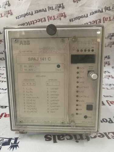
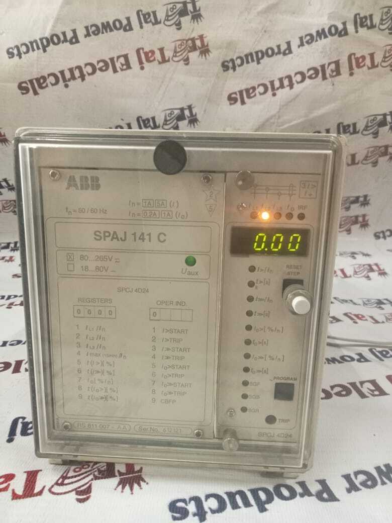
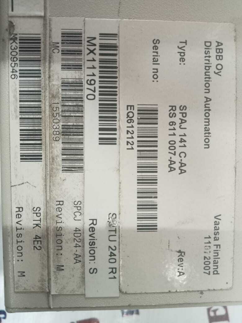

 Send Inquiry